You will rarely need to take
current measurements, however most multimeters have DC current ranges
such as 0.5mA, 50mA, 500mA and 10Amp (via the extra banana socket)
and some meters have AC current ranges. Measuring the current of a circuit will tell you a lot of things.
If you know the normal current, a high or low current can let you know if
the circuit is overloaded or not fully operational.
Current is always measured when the circuit is working (i.e: with power applied).
It is measured IN SERIES with the circuit or component under test.
The easiest way to measure current is to remove the fuse and take a reading across the fuse-holder. Or remove one lead of the battery or turn the project off, and measure across the switch.
If this is not possible, you will need to remove one end of a component and measure with the two probes in the "opening."
Resistors are the easiest things to desolder, but you may have to cut a track in some circuits. You have to get an "opening" so that a current reading can be taken.
The following diagrams show how to connect the probes to take a CURRENT reading.
Do not measure the current ACROSS a component as this will create a "short-circuit."
The component is designed to drop a certain voltage and when you place the probes across this component, you are effectively adding a "link" or "jumper" and the voltage at the left-side of the component will appear on the right-side. This voltage may be too high for the circuit being supplied and the result will be damage.
Measuring current through a resistor
Measuring the current of a globe
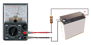
Do NOT measure the
CURRENT of a battery
(by placing the meter directly across the terminals)
A battery will deliver a very HIGH current
and damage the meter
(by placing the meter directly across the terminals)
A battery will deliver a very HIGH current
and damage the meter
Do not measure the "current a battery will deliver" by placing the probes
across the terminals. It will deliver a very high current and damage the
meter instantly. There are special battery testing instruments for this
purpose.
When measuring across an "opening" or "cut," place the red probe on the wire that supplies the voltage (and current) and the black probe on the other wire. This will produce a "POSITIVE" reading.
A positive reading is an UPSCALE READING and the pointer will move across the scale - to the right. A "NEGATIVE READING" will make the pointer hit the "STOP" at the left of the scale and you will not get a reading. If you are using a Digital Meter, a negative sign "-" will appear on the screen to indicate the probes are around the wrong way. No damage will be caused. It just indicates the probes are connected incorrectly.
If you want an accurate CURRENT MEASUREMENT, use a digital meter.


No comments:
Post a Comment