In this project, I will talk about Shift Registers, one of the popular Shift Register ICs – 74HC595 and finally how to use the 74HC595 Shift Register with Arduino and the benefits of this interface.
Introduction
Normally, consider a small application where you want to drive 8 LEDs with the help of Arduino (or any microcontroller). This application, though a very basic and simple one, would require you to use 8 of the available Input / Output Pins of your Arduino Board: one for each LED.
Now consider a slightly advanced project, where your requirements are driving the same 8 LEDs and also doing other stuff like displaying a message or any information on a 16×2 LCD Display or interface a Bluetooth Device to control the LEDs through a smart phone!!!
This type of bigger projects would consume a lot of your I/O Pins on your Arduino Board and there might not be enough pins left for interfacing additional devices.
Here comes the Shift Register IC to the rescue.
What is a Shift Register?
A Shift Register is basically a Serial-to-Parallel Converter IC. It basically takes a serial input through a single pin (well, technically you need at least 3 pins, which I will talk about later) and converts it into 8-bit parallel output thus effectively reducing the number of interface pins between a Microcontroller and its output devices.
There are other flavours of shift registers like Serial IN Parallel OUT (the one we are interested in), Serial IN Serial OUT, Parallel IN Serial OUT and Parallel IN Parallel OUT. For more information on Shift Registers, visit SHIFT REGISTERS TYPES AND APPLICATIONS.
In this project, I will be using a Serial IN and Parallel OUT type Shift Register IC called 74HC595.
A Brief Note 74HC595 Shift Register IC
As mentioned earlier, the 74HC595 IC is an 8-bit Serial IN Parallel OUT shift register. It is 16-pin IC available in a wide range of packages like DIP, SOIC, SSOP and TSSOP.
Pin Diagram of 74HC595 Shift Register
The following image shows the Pin Diagram of 74HC595 Shift Register.
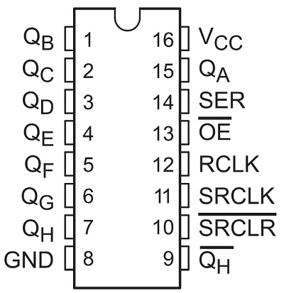
Pin Description of 74HC595 Shift Register
Following table describes the pins of 74HC595 Shift Register in brief.
| Pin Number | Pin Name | Description |
| 15, 1-7 | QA, QB – QH | QA – QH (8) Output Pins |
| 8 | GND | Ground Pin |
| 9 | QH’ | QH’ Output |
| 10 | SRCLR’ | Reset Input |
| 11 | SRCLK | Clock Input |
| 12 | RCLK | Storage Register Clock Input |
| 13 | OE’ | Output Enable |
| 14 | SER | Serial Input |
| 16 | VCC | Supply Voltage |
NOTE: There are several manufacturers of 74HC595 Shift Register IC and the naming convention of each manufacturer may be different. Check out the data sheet based on the manufacturer. The above pin names are from the data sheet provided by Texas Instruments.
How to use 74HC595 Shift Register with Arduino?
Let me build a simple circuit where I will use only three pins of Arduino UNO and control 8 LEDs. This will be possible by using the 74HC595 Shift Register with Arduino.
The three pins of the shift register that are needed to be connected to Arduino are pins 11 (the clock input), 12 (the storage register clock input or simply the latch input) and 14 (the data input).
All the 8 LEDs will be connected to the shift register IC. (more details in the circuit design section).
Circuit Diagram
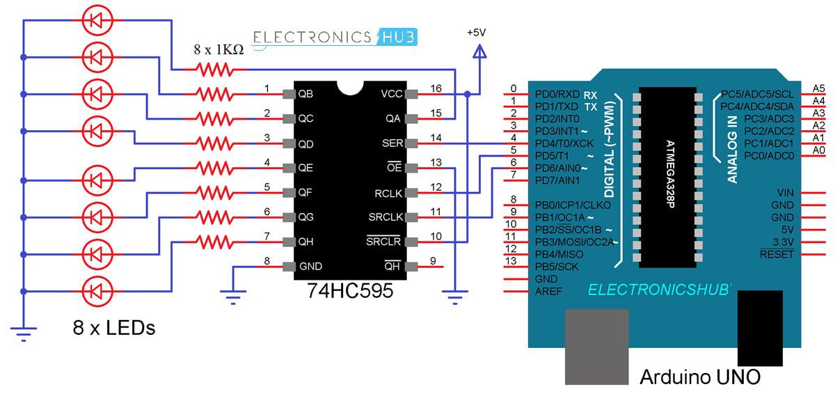
The following image shows the circuit diagram of interfacing 74HC595 Shift Register with Arduino UNO.
Components Required
- Arduino UNO
- 74HC595 Shift Register IC
- Breadboard
- 8 X LEDs
- 8 X 1KΩ Resistors
- 5V Power Supply
- Connecting Wires
Circuit Design
First, connect the Serial Input Pin of 74HC595 Shift Register to Pin 4 of Arduino. Then connect the clock and latch pins i.e. pins 11 and 12 of 74HC595 to pins 6 and 5 of Arduino respectively.
Now, connect 8 LEDs with individual current limiting 1KΩ Resistors to the 8 output pins of 74HC595 IC. Coming to the power supply, connect a separate 5V power supply to 74HC595 IC with common GND to Arduino rather than supplying 5V from Arduino.
Code
The following is a simple code for turning the LEDs ON in a sequence.
Working
Let us now try to understand the working of this project. Initially, all the LEDs will be OFF as the byte variable LED is set to 0. Now, each bit is set to 1 using the “bitSet” function and is shifted out using the “shiftOut” function.
Correspondingly, each LED will be turned on in the same sequence. If you want to turn the LED off, you can use the “bitClear” function.
Applications
The 74HC595 Shift Register IC or any similar shift register for that matter can be used in the following applications:
- LED Control
- Network Switches
- Servers
- Power Infrastructure
- Industrial Control
- Electronic Appliances
- Simple Serial-to-Parallel Data Conversion
- Capture and Hold Logic
The post How to use 74HC595 Shift Register with Arduino? appeared first on Electronics Hub.
from Electronics Hub https://ift.tt/2NGRxTq


No comments:
Post a Comment