Search This Blog

Tuesday, October 30, 2018

What is a Photodiode? Working, Characteristics, Applications

What is a Photodiode?

It is a form of light-weight sensor that converts light energy into electrical voltage or current. Photodiode is a type of semi conducting device with PN junction. Between the p (positive) and n (negative) layers, an intrinsic layer is present. The photo diode accepts light energy as input to generate electric current.

It is also called as Photodetector, photo sensor or light detector. Photo diode operates in reverse bias condition i.e. the p – side of the photodiode is connected with negative terminal of battery (or the power supply) and n – side to the positive terminal of battery.

Typical photodiode materials are Silicon, Germanium, Indium Gallium Arsenide Phosphide and Indium gallium arsenide.

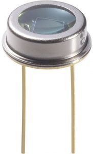
Internally, a photodiode has optical filters, built in lens and a surface area. When surface area of photodiode increases, it results in more response time. Few photo diodes will look like Light Emitting Diode (LED). It has two terminals as shown below. The smaller terminal acts as cathode and longer terminal acts as anode.

Photodiode Image

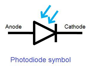
The symbol of the photodiode is similar to that of an LED but the arrows point inwards as opposed to outwards in the LED. The following image shows the symbol of a photodiode.

Photodiode Symbol

Working of a Photodiode

Generally, when a light is made to illuminate the PN junction, covalent bonds are ionized. This generates hole and electron pairs. Photocurrents are produced due to generation of electron-hole pairs. Electron hole pairs are formed when photons of energy more than 1.1eV hits the diode. When the photon enters the depletion region of diode, it hits the atom with high energy. This results in release of electron from atom structure. After the electron release, free electrons and hole are produced.

Photodiode Working

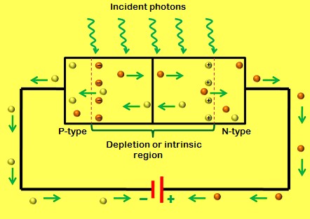
In general, an electron will have negative charge and holes will have a positive charge. The depletion energy will have built in electric filed. Due to that electric filed, electron hole pairs moves away from the junction. Hence, holes move to anode and electrons move to cathode to produce photo current.   The photon absorption intensity and photon energy are directly proportional to each other. When energy of photos is less, the absorption will be more. This entire process is known as Inner Photoelectric Effect.

Intrinsic Excitations and Extrinsic Excitations are the two methods via which the photon excitation happens. The process of intrinsic excitation happens, when an electron in the valence band is excited by photon to conduction band.

Also read “Different Types of Sensors

Modes of operation of a Photo Diode

Photodiode operates in three different modes namely Photovoltaic mode, Photoconductive mode and Avalanche diode mode.
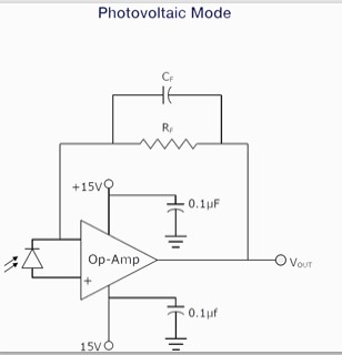
Photovoltaic Mode

This is otherwise called as Zero Bias mode. When a photodiode operates low frequency applications and ultra-level light applications, this mode is preferred. When photodiode is irradiated by flash of light, voltage is produced. The voltage produced will be in very small dynamic range and it has a non-linear characteristic. When photodiode is configured with OP-AMP in this mode, there will be a very less variation with temperature.

Photodiode Photovoltaic Mode

Photoconductive Mode

In this mode, photodiode will act in reverse biased condition. Cathode will be positive and anode will be negative. When the reverse voltage increases, the width of the depletion layer also increases. Due to this the response time and junction capacitance will be reduced. Comparatively this mode of operation is fast and produces electronic noise.

Photodiode Photoconductive Mode

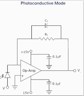
Transimpedance amplifiers are used as preamplifiers for photodiodes. Modes of Such amplifiers keep the voltage maintains to be constant to make photo diode operate in the photoconductive mode.

Avalanche Diode Mode

In this mode, avalanche diode operates at a high reverse bias condition. It allows multiplication of an avalanche breakdown to each photo-produced electron-hole pair. Hence, this produces internal gain within photodiode. The internal gain increases the device response.

Connecting a Photodiode in an External Circuit

A photodiode operates in a circuit in reverse bias. Anode is connected to circuit ground and cathode to positive supply voltage of the circuit. When illuminated by light, current flows from cathode to anode.

Photodiode Circuit Connection

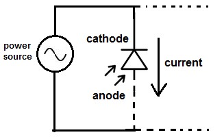
When photodiodes are used with external circuits, they are connected to a power source in the circuit. The amount of current produced by a photodiode will be very small. This value of current will not be enough to drive an electronic device. So when they are connected to an external power source, it delivers more current to the circuit. So, battery is used as a power source. The battery source helps to increase the current value, which helps the external devices to have a better performance

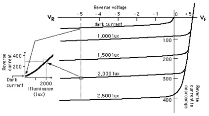
V-I Characteristics of Photodiode

Photodiode operates in reverse bias condition. Reverse voltages are plotted along X axis in volts and reverse current are plotted along Y-axis in microampere. Reverse current does not depend on reverse voltage. When there is no light illumination, reverse current will be almost zero. The minimum amount of current present is called as Dark Current. Once when the light illumination increases, reverse current also increases linearly.

Photodiode V-I Characteristics

Applications of Photodiode

  • In a simple day to day applications, photodiodes are used. The reason for their use is their linear response of photodiode to a light illumination. When more amount of light falls on the sensor, it produces high amount of current. The increase in current will be displayed on a galvanometer connected to the circuit.
  • Photodiodes helps to provide an electric isolation with help of optocouplers. When two isolated circuits are illuminated by light, optocouplers is used to couple the circuit optically. But the circuits will be isolated electrically. Compared to conventional devices, optocouplers are fast.
  • Photodiodes are applied in safety electronics like fire and smoke detectors. It is also used in TV units.
  • When utilized in cameras, they act as photo sensors. It is used in scintillators charge-coupled devices, photoconductors, and photomultiplier tubes.
  • Photodiodes are also widely used in numerous medical applications  like instruments to analyze samples, detectors for computed tomography and also used in blood gas monitors.


The post What is a Photodiode? Working, Characteristics, Applications appeared first on Electronics Hub.


from Electronics Hub https://ift.tt/2zem4yE

Saturday, October 27, 2018

LCD LED TV BIOS CHIP FIRMWARE - SOFTWARE DOWNLOAD

V59 ALL RESOLUTION SOFTWARE FIRMWARE

DOWNLOAD 


INTEX LCD LED TV BIOS FIRMWARE / SOFTWARE DOWNLOADS


INTEX LED TV LE 19HD06-BO13 Bios Firmware / Software - DOWNLOAD

INTEX LED TV LE 19HD08-BO13 BIOS FIRMWARE / SOFTWARE - DOWNLOAD

INTEX LED TV LE 20HDR06-ME13 (MEPL) BIOS FIRMWARE / SOFTWARE - DOWNLOAD

INTEX LED TV LE22FHD07-VR12 BIOS FIRMWARE / SOFTWARE – DOWNLOAD

INTEX LED TV LE22FHD07-VR12, LG Panel BIOS FIRMWARE / SOFTWARE – DOWNLOAD

INTEX LED TV LE23HDR05-VT13  BIOS FIRMWARE / SOFTWARE – DOWNLOAD

INTEX LED TV LE 23HDR06-ME13 BIOS FIRMWARE / SOFTWARE - DOWNLOAD

INTEX LED TV LE 24FHD07-BO13 BIOS FIRMWARE / SOFTWARE - DOWNLOAD

INTEX LED TV LE 31HD08-BO13 BIOS FIRMWARE / SOFTWARE - DOWNLOAD

INTEX LED TV LE 31HD08-BO14 BIOS FIRMWARE / SOFTWARE - DOWNLOAD

INTEX LED TV LE 40FHD07-VM13 BIOS FIRMWARE / SOFTWARE - DOWNLOAD

INTEX LED TV LED 1601-ME13 BIOS FIRMWARE / SOFTWARE - 
DOWNLOAD

INTEX LED TV LED 1602-TR14 23rd BIOS FIRMWARE / SOFTWARE - DOWNLOAD

INTEX LED TV LED-1602N BIOS FIRMWARE / SOFTWARE – DOWNLOAD

INTEX LED TV LED 1610-VT13 (Videotex) BIOS FIRMWARE / SOFTWARE - DOWNLOAD

INTEX LED TV LED 1611-VT13 (Videotex) BIOS FIRMWARE / SOFTWARE – DOWNLOAD

INTEX LED TV LED 1612 -VT13 new BIOS FIRMWARE / SOFTWARE – DOWNLOAD

INTEX LED TV LED 1612-VT13 (W) (Videotex) BIOS FIRMWARE / SOFTWARE-  DOWNLOAD

INTEX LED TV LED-1901-LG- BIOS FIRMWARE / SOFTWARE – DOWNLOAD

INTEX LED TV LED-1901-SHARP BIOS FIRMWARE / SOFTWARE – DOWNLOAD

INTEX LED TV LED-1910 BIOS FIRMWARE / SOFTWARE – DOWNLOAD

INTEX LED TV LED 2201 (VMI) BIOS FIRMWARE / SOFTWARE – DOWNLOAD

INTEX LED TV LED-2110 BIOS FIRMWARE / SOFTWARE – DOWNLOAD

INTEX LED TV LED-2205 BIOS FIRMWARE / SOFTWARE – DOWNLOAD

INTEX LED TV LED-2207 BIOS FIRMWARE / SOFTWARE – DOWNLOAD

INTEX LED TV LED-2208 FHD BIOS FIRMWARE / SOFTWARE – DOWNLOAD

INTEX LED TV LED-2302 BIOS FIRMWARE / SOFTWARE – DOWNLOAD

INTEX LED TV LED-G2401 BIOS FIRMWARE / SOFTWARE – DOWNLOAD

INTEX LED TV LED-2810 BIOS FIRMWARE / SOFTWARE – DOWNLOAD

INTEX LED TV LED-2812 BIOS FIRMWARE / SOFTWARE – DOWNLOAD

INTEX LED TV LED-2901 BIOS FIRMWARE / SOFTWARE – DOWNLOAD

INTEX LED TV LED-3105T BIOS FIRMWARE / SOFTWARE – DOWNLOAD

INTEX LED TV LED 3106-V13 (DLED) BIOS FIRMWARE / SOFTWARE – DOWNLOAD

INTEX LED TV LED-3110 BIOS FIRMWARE / SOFTWARE – DOWNLOAD

INTEX LED TV LED-3110 BIOS FIRMWARE / SOFTWARE – DOWNLOAD

INTEX LED TV LED-3199 GOLD BIOS FIRMWARE / SOFTWARE – DOWNLOAD

INTEX LED TV LED-3200SB BIOS FIRMWARE / SOFTWARE – DOWNLOAD

INTEX LED TV LED3204V12+LG-LC320EXNSDA1 BIOS FIRMWARE / SOFTWARE - DOWNLOAD

INTEX LED TV LED3204V12+LG-LC320EXNSEA3 BIOS FIRMWARE / SOFTWARE – DOWNLOAD

INTEX LED TV LED3204V12+SAMSUNG-LTA320AN12 BIOS FIRMWARE / SOFTWARE – DOWNLOAD

INTEX LED TV LED 3206-V13 BIOS FIRMWARE / SOFTWARE -  DOWNLOAD

INTEX LED TV LED-3210 Thik LVDS BIOS FIRMWARE / SOFTWARE – DOWNLOAD

INTEX LED TV LED-3210 Thin LVDS BIOS FIRMWARE / SOFTWARE – DOWNLOAD

INTEX LED TV LED-3211 BIOS FIRMWARE / SOFTWARE – DOWNLOAD

INTEX LED TV LED 3212 HD (MEPL) BIOS FIRMWARE / SOFTWARE – DOWNLOAD

INTEX LED TV LED-3213 BIOS FIRMWARE / SOFTWARE – DOWNLOAD

INTEX LED TV LED-3215 BIOS FIRMWARE / SOFTWARE – DOWNLOAD

INTEX LED TV LED-3218 BIOS FIRMWARE / SOFTWARE – DOWNLOAD

INTEX LED TV BIG LED-3219 LVDS BIOS FIRMWARE / SOFTWARE – DOWNLOAD

INTEX LED TV LED 3220 BOI BIOS FIRMWARE / SOFTWARE – DOWNLOAD

INTEX LED TV LED 3220 (SAMSUNG ) BIOS FIRMWARE / SOFTWARE – DOWNLOAD

INTEX LED TV LED-3220 BIOS FIRMWARE / SOFTWARE – DOWNLOAD

INTEX LED TV LED-3221 Panel with additional TCON board BIOS FIRMWARE / SOFTWARE – DOWNLOAD
INTEX LED TV LED-3221 Panel without additional TCON board BIOS FIRMWARE / SOFTWARE – DOWNLOAD

INTEX LED TV LED-40FHD10VM (1) BIOS FIRMWARE / SOFTWARE – DOWNLOAD

INTEX LED TV LED-40FHD10VM (2) BIOS FIRMWARE / SOFTWARE – DOWNLOAD

INTEX LED TV LED-40FHD10VM (3) BIOS FIRMWARE / SOFTWARE – DOWNLOAD

INTEX LED TV LED-4016 BIOS FIRMWARE / SOFTWARE – DOWNLOAD

INTEX LED TV LED-4018 BIOS FIRMWARE / SOFTWARE – DOWNLOAD

INTEX LED TV LED-4200 FHD BIOS FIRMWARE / SOFTWARE – DOWNLOAD

INTEX LED TV LED-4200FHD BIOS FIRMWARE / SOFTWARE – DOWNLOAD

INTEX LED TV LED-4300FHD BIOS FIRMWARE / SOFTWARE – DOWNLOAD

INTEX LED TV SW 5000 FHD BIOS FIRMWARE / SOFTWARE – DOWNLOAD

INTEX LED TV LED-5010FHD BIOS FIRMWARE / SOFTWARE – DOWNLOAD

INTEX LCD TV LC22HDR BIOS FIRMWARE / SOFTWARE – DOWNLOAD

INTEX LCD TV LC22HDR12-VT12 BIOS FIRMWARE / SOFTWARE - DOWNLOAD

INTEX LCD TV LC32HRUM2-KT11 BIOS FIRMWARE / SOFTWARE – DOWNLOAD

INTEX LCD TV LC32HRUM2-KT11 BIOS FIRMWARE / SOFTWARE – DOWNLOAD

INTEX LCD TV LC32KT11 & LC32T72 BIOS FIRMWARE / SOFTWARE – DOWNLOAD

INTEX LCD TV LCD 3201-KT11  BIOS FIRMWARE / SOFTWARE - DOWNLOAD

INTEX LCD TV LCD 3201 BIOS FIRMWARE / SOFTWARE – DOWNLOAD

INTEX LCD TV LCD 3272T (LG) BIOS FIRMWARE / SOFTWARE – DOWNLOAD

INTEX LCD TV LCD 3272T-SAMSUNG BIOS FIRMWARE / SOFTWARE – DOWNLOAD

INTEX LCD TV LCD 4001 BIOS FIRMWARE / SOFTWARE – DOWNLOAD

INTEX LCD TV LCD 4072 BIOS FIRMWARE / SOFTWARE – DOWNLOAD

INTEX LCD TV LCD 4073 BIOS FIRMWARE / SOFTWARE – DOWNLOAD


OTHER BRAND FIRMWARE ARE AVAILABLE HERE


If require other bios firmware software in intex led lcd tv you can write me comment box I will try to collect .Thanks for visit............


IN FEW SOME DAY LATER OTHER BRAND AND MODEL SOFTWARE ARE UPDATE.....

Friday, October 26, 2018

LG 22LN4305 PT on standby

motherboard board
pannel
flap

fault standby not release
main ic fault A7MK669C
Problem solved

Sunday, October 14, 2018

Brand wise chroma ic used in color tv no as ...

LG

TDA11105 PS/N3/3/AN4
TDA 9381PS/N2/310955
TDA 9370 PS /N3/A/1743
TDA 8842 -S1


SAMSUNG

MODEL - CZ 20D8V
TDA 9381PS/N2/3/0660

MODEL- CZ 20E4V
TDA 9381PS/N2/3/310877

MODEL - CS14C540AJNXXL
TDA 11105H/N3/3

MODEL - CB21K5ML

MODEL - CS21A530FLKXL
TDA 12156H/N3/3

MODEL - CS 14D600KJ
TDA11105H/N3/3

MODEL - CB5001FV
SYSTEM - KS88C8432-11 SSM-501E1
CHORMA- TDA 8841 S1

MODEL -FLAT
TDA1113GPS/N3/3


SANSUI


MODEL - FIRATTO -21
CHORMA - 8823CPNG4PB8

MODEL - DHANAPURNA 20 TS
 CHORMA - 8823CPNG4RJ1

MODEL - DHANAPURNA 14KV
SYSTEM - LC863332A 5R58
CHROMA - LA76810A

MODEL - FIRST 14-OP
CHORMA - TSB2/VER01  8823CPNG5HK5

MODEL - CHIC CLASSIC 200
CHORMA - NT 11135PC310CC

MODEL - CTV B2B 21V
CHROMA - TDA 12135PS/N3/3/AE8

MODEL - VIVA 14 SAN14MSP-CNT
CHORMA - ROC-VAS-02   R2J10160G8-A61

MODEL - SV2010K
SYSTEM - LC8633340A 5Y37 2C02
CHORMA - LA76810A

MODEL - SY-14 SUPER EYE P
CHROMA - TDA9370PS/N3/A/0932


ONIDA


MODEL - PROMISE-14
CHORMA - M37220M3-201 SP

MODEL - CO21VIP300B
CHORMA - TDA11135H/N3/37AK1

MODEL -
CHORMA - M37160MA-200FP

MODEL -
CHROMA - M52771ASP

MODEL - CLASSIC CI14PIUTG
CHORMA - 623Z04 M61266

MODEL - CLASSIC 14 / CI14PIUPGS
CHORMA - TDA11105H/N3/3/MB3

MODEL - IGO 20XS
SYSTEM - M7221M6-261SP
CHORMA - M52778SP A

MODEL - ULTRASLIM -250 / CI21SMP250B-R
CHROMA - TDA12155H/N3/3/AK3

MODEL -  20XS DLX
CHORMA - M81265


BESTAVISION


SYSTEM - LC863528C
CHROMA - LA76818A

LC863528C

8823CSNG6G81


BUSH

 MODEL - FIRE P
CHORMA - LA76810B
SYSTEM - LC863528B

VIDEOCON


MODEL - SOUL 200
CHROMA - TDA1105PS/V3/3/AH6

MODEL -
SYSTEM - 7B268 VH
CHORMA - TDA9370PS/N3/A/1930

MODEL - CHAMP 20 / VAN 20 ESP -CNK
CHROMA - ROC VAS 05 R2J10160G8-A72

MODEL - AVIVA
CHROMA - ROC VAS 11R2 R2J10160G8 A84

MODEL CHAMP 14 / CTVVBN14MPF-CNT
MODEL NEXT NX 11508CF
CHORMA - LA76931K 71 5AP3

MODEL - VTV VHN14MBF-CNA
LA7693K 7N 5AZ9

MODEL -  CTV VAN 20SGB-CNT
CHROMA-  R2J10172HA-A00FP

MODEL - VBF21SDV-CFU
CHROMA - TDA1213PS/V3/3/AH4

SVL


MODEL - SLIMLINE 15
CHROMA - LA76931S 7N

MODEL - SIGMA 14M
CHROMA - TDA11105PS/V3/3/A04

MODEL - SOLO 20
CHROMA - LA76931S 7N 59F8

MODEL - PLATINUM 14
SYSTEM - TDA11105PS/V3/3/A0B

TEXLA

CHORMA - 8873CSCNGPR6

MODEL - 2921E
CHROMA - LA76818A
SYSTEM - LC863540B 51F9

PHILIPS


CHROMA - TDA8841S1
SYSTEM - SAA5533PS/M4/0/63

MODEL - TDA9370PS/N3/A/1665

MODEL -
CHROMA - TDA9373PS/N3/A

MODEL - 14PT2117/94
CHROMA - TDA9370PS/N3/A

MODEL - 14PTS626/V7
CHROMA -  TDA111PS/V3/3      NT11105PC380AG

MODEL - 29PT2452/94S
CHROMA- TDA9599H/N1/4

MODEL - 21PT3626/V7
CHROMA - NT1215PC380AG

MODEL - 21PT4327/V7
CHROMA - TDA12135/PS/N3/3/MD3

MODEL -  14PT3624/V7
CHROMA -  NT11105PC356AG


Thursday, October 4, 2018

LG MODEL 14SA2BB-AJ CIRCUT DETAILS

CHROMA = 11105PS/N3 /3/ AN4
SMPS = STR W6754
SMPS TRANSFORMER = EBJ41486706
VERTICAL= LA78141
AUDIO = TDA 7297SA
HORIZONTAL OUT PUT = D5023
EHT =
HOR OSC COIL = EBJ 40924203
TUNNER = TAEA G023D
REMOTE = 6710V00109
SERVICE MODE = PANNEL MENU +REMOTE MENU

Automatic Road Reflector Light

Download Project Document/Synopsis The Automatic Road Reflector is a simple but effective system will help us automate the traditional road reflectors. A raised pavement marker is a safety device used on road to guide the vehicles along the path at the time of night. The Automatic Road Reflector system is designed to replace this currently […]

from NevonProjects https://ift.tt/2RkmUC2

Wednesday, October 3, 2018

Smart Dustbin using Arduino, Ultrasonic Sensor & Servo Motor

In this project, I will show you How to Make a Smart Dustbin using Arduino, where the lid of the dustbin will automatically open when you approach with trash. The other important components used to make this Smart Dustbin are an HC-04 Ultrasonic Sensor and an SG90 TowerPro Servo Motor.

How to Make a Smart Dustbin using Arduino Image 7

Introduction

Dustbins (or Garbage bins, Trash Cans, whatever you call them) are small plastic (or metal) containers that are used to store trash (or waste) on a temporary basis. They are often used in homes, offices, streets, parks etc. to collect the waste.

In some places, littering is a serious offence and hence Public Waste Containers are the only way to dispose small waste.

Usually, it is a common practice to use separate bins for collecting wet or dry, recyclable or non-recyclable waste.

In this project, I have designed a simple system called Smart Dustbin using Arduino, Ultrasonic Sensor and Servo Motor, where the lid of the dustbin will automatically open itself upon detection of human hand.

Concept behind Smart Dustbin using Arduino

The main concept behind the Smart Dustbin using Arduino project is Object Detection. I have already used Ultrasonic Sensor in Object Avoiding Robot, where upon detecting an object, the Robot will change its course of direction.

A similar methodology is implemented here, where the Ultrasonic Sensor is placed on top of the dustbin’s lid and when the sensor detects any object like a human hand, it will trigger Arduino to open the lid.

How to Build a Smart Dustbin using Arduino?

Connecting the Servo

Now, let me take you through the actual setup and build process of the Smart Dustbin using Arduino. First, I will start with the mechanism to open the lid. As you might have already guessed, I have used a Servo Motor for this purpose.

In order to open the lid, I have fixed a small plastic tube (like an empty refill of a ball-point pen) to the servo horn (a single ended horn) using instant glue.

How to Make a Smart Dustbin using Arduino Image 1

For this mechanism to be able to open the lid of the dustbin, it must be placed near the hinge where the lid is connected to the main can. From the following image, you can see that I have fixed the servo motor on the can.

Also, make sure that the lifting arm is parallel to ground under closed lid condition.

How to Make a Smart Dustbin using Arduino Image 2

NOTE: According to the Laws of Physics, you will require more energy to push the lid from the hinge than at the extreme end. But in order to open the lid and not have any obstacle, this is the only place to fix the servo motor with its arm.

Connecting the Ultrasonic Sensor

Once the servo is in position, you can move onto the Ultrasonic Sensor. Make two holes corresponding to the Ultrasonic Sensor on the lid of the dustbin, as shown in the following image.

How to Make a Smart Dustbin using Arduino Image 3

WARNING: You have to use a sharp object with a lot of force to make these holes. Be careful.

Now, from the inside, place the Ultrasonic Sensor through the holes and fix its position with the help of glue.

How to Make a Smart Dustbin using Arduino Image 4

Wiring up the Components

The final step in the build process is to make the necessary connections using long connecting wires as per the circuit diagram and securing these wires so that they don’t hang around.

How to Make a Smart Dustbin using Arduino Image 5

All the wires from both the components i.e. Ultrasonic Sensor and Servo Motor are connected to respective pins of Arduino. This finishes up the build process of the Smart Dustbin.

How to Make a Smart Dustbin using Arduino Image 6

Circuit Diagram

The following image shows the circuit diagram of the Smart Dustbin using Arduino. It is a very simple design as the project involves only two components other than Arduino.

How to Make a Smart Dustbin using Arduino Circuit Diagram

Components Required

  • Arduino UNO
  • HC-SR04 Ultrasonic Sensor Module
  • TowerPro SG90 Servo Motor
  • Connecting Wires
  • 5V Power Supply
  • A small dustbin with hinged lid
  • Miscellaneous (glue, plastic tube, etc.)

Code

The code for the project How to Smart Dustbin using Arduino is given below.

Working

After setting up the Smart Dustbin and making all the necessary connections, upload the code to Arduino and provide 5V power supply to the circuit. Once the system is powered ON, Arduino keeps monitoring for any object near the Ultrasonic Sensor.

If the Ultrasonic Sensor detects any object like a hand for example, Arduino calculates its distance and if it less than a certain predefined value, Arduino will activate the Servo Motor and with the support of the extended arm, it will list the lid open.

After certain time, the lid is automatically closed.  

Conclusion

 A simple but useful project called Smart Dustbin using Arduino is designed and developed here. Using this project, the lid of the dustbin stays closed, so that waste is not exposed (to avoid flies and mosquitos) and when you want dispose any waste, it will automatically open the lid.

The post Smart Dustbin using Arduino, Ultrasonic Sensor & Servo Motor appeared first on Electronics Hub.


from Electronics Hub https://ift.tt/2DPQ49G

Monday, October 1, 2018

Electric Flux and Gauss’s Law

In this lecture we will learn about Electric Flux and Gauss’s Law. In electrostatics, the primary goal of Gauss’s law is to find the electric field for a given charge distribution, enclosed by a closed surface.

You can watch the following video or read the written tutorial below the video.

Electric Flux

In order to understand Gauss’s Law, first we need to understand the term Electric flux.

Electric flux is the rate of flow of the electric field through a given surface.

It is the amount of electric field penetrating a surface. And that surface can be open or closed.

Electric Flux through Open Surfaces

First, we’ll take a look at an example for electric flux through an open surface.

1.Electric Flux and Gauss's Law - Electric Flux through an Open Surface

The red lines represent a uniform electric field. We will bring in that field a rectangle, which is an open area, and we will divide it into very small elements, each with size dA (differential of area).

Now we’re going to make the area dA a vector, with a magnitude dA. The vector direction is always perpendicular to the small element dA.

2.Electric Flux and Gauss's Law - Differential of Flux Formula

The electric flux that passes through this small area dφ,  (also called a differential of flux), is defined as a dot product of the magnitude of the electric field E and the magnitude of the vector area dA, times the angle between these two vectors θ.

3.Electric Flux and Gauss's Law - Total Flux Formula

The total flux is going to be the integral of dφ, or the integral over that entire area of E·dA.

It is a scalar quantity and the end result can be positive or negative. If the flux is going from the inside to the outside, we call that a positive flux, if it is going from the outside to the inside, that’s a negative flux.

4.Electric Flux and Gauss's Law - Electric Flux Unit of Measurement

The unit of electric flux is Newton meters squared per Coulomb (Nm2/C).

5.Electric Flux and Gauss's Law - 3 Rectangles with Different Orientation into an Electric Field

To get a better understanding of what electric flux is, I’ll bring into this electric field three rectangles. In fact, these rectangles represent one rectangle with different orientations. Now let’s explain the flux through each one of those open areas.

6.Electric Flux and Gauss's Law - Parallel Area Vector and Electric Field Vector - Maximum Flux

In the first case, the area is perpendicular to the electric field, and the angle between their vectors θ is 0°. Cos0° is 1, so the electric flux is going to be EdA. Here we have maximum flux.

7.Electric Flux and Gauss's Law - Area Vector and Electric Field Vector at an Angle

In the second case, the angle between E and dA θ is 60°, and cos60° is 0.5, so the electric flux will be half EdA.

8.Electric Flux and Gauss's Law - Perpendicular Area Vector and Electric Field Vector - Zero Flux

In the third case, the area is parallel to the electric field, which means that their vectors are perpendicular to each other, and the angle θ between them is 90°. Cos90° is 0, so the electric flux here will be 0. This means that nothing goes through that rectangle, so her we have zero flux.

Related: Coulomb’s Law

Electric Flux through Closed Surfaces

Now, let’s take a look at a surface that is completely closed.

9.Electric Flux and Gauss's Law - Electric Flux through Closed Surfaces

How do we define flux?

Here, we put some normals, dAs in different directions. By convention, the normal to the closed surface always points from the inside to the outside.

10.Electric Flux and Gauss's Law - Total Flux Formula for Closed Surface Formula

Now we can calculate the total flux going through this closed surface. The total flux is equal to the integral of dφ over that entire surface, which we write as the integral over that closed surface of E·dA.

The total flux can be positive, negative, or equal to zero. If the same amount of flux is entering and leaving the surface, we have zero total flux. If more flux is leaving than entering the surface, then we have positive total flux. Opposite, if more flux is entering than leaving the surface, we have a negative total flux.

Gauss’s Law

Let’s take a look at another example, and see how the electric flux is related to Gauss’s Law.

11.Electric Flux and Gauss's Law - Point Charge in the Center of a Sphere

We have a point charge +Q in the center of a sphere with radius R. Now, we’ll take a small segment dA, which vector is perpendicular to the surface and is radially outward. The electric field generated by Q at that point is also radially outward. This means that dA and E anywhere on the surface of this sphere are parallel to each other, the angle between them θ is 0°, and cos0° is 1.

12.Electric Flux and Gauss's Law - Differential of Flux through a Sphere Formula

The differential of flux through the small surface area, dφ is equal to EdA.

13.Electric Flux and Gauss's Law - Total Flux through a Sphere Formula

The total flux Φ is going to be the integral of dφ, which is the integral over the closed surface EdA. The magnitude of the electric field everywhere is the same, because the distance from the charge is the same at each point, so we can pull that out of the integral, and we’re left with EA.

14.Electric Flux and Gauss's Law - Total Area of a Sphere Formula

The total area of the sphere A is 4πR2.

15.Electric Flux and Gauss's Law - Electric Field Formula

From the previous videos we know that E is equal to k times Q divided by r2, which is equal to Q divided by 4πE0R2.

16.Electric Flux and Gauss's Law - Total Flux through a Sphere Derived Formula

And the total flux through this closed surface is simply E times 4πR2. Here we can cancel out 4πR2, and we can notice that the total flux is equal to Q divided by E0, where E0 is permittivity of free space.

The flux doesn’t depend on the distance r. We would get the same result no matter the size of the closed surface around the point charge.

What if we bring more charges inside the closed surface?

The equation should also hold for any system of charges inside.

17.Electric Flux and Gauss's Law - Total Flux through a Sphere with a System of Charges Formula

This leads us to the Gauss’s Law, which says that the electric flux going through a closed surface, is the sum of all charges Q inside that closed surface, divided by permittivity of free space E0.

If that flux is zero, that means there is no net charge inside the shape. There could be positive and negative charges inside the shape, but the net is zero.

No matter how weird the shape, Gauss’s Law always holds, as long as there’s a symmetry in the charge distribution inside the surface.

So, in order to calculate the electric field, you need a symmetry. And there are three types of symmetry: spherical, cylindrical and planar symmetry.

Related: What is Electric Charge and How Electricity Works

Spherical Symmetry: Electric Field due to a Point Charge

We will start with spherical symmetry.

18.Electric Flux and Gauss's Law - Spherical Symmetry - Electric Field Due to a Point Charge

This is a thin hollow sphere, with a radius R, and we’ll bring a positive charge Q onto the thin shell. The charge is uniformly distributed.

19.Electric Flux and Gauss's Law - Spherical Symmetry - Electric Field Due to a Point Charge 2

Now, we need to find the electric field inside the sphere, at a distance R1 from the center, and outside the sphere, at a distance R2 from the center. To do that, we need to determine our Gaussian surface. In this case, we will choose concentric spheres as Gaussian surfaces, one smaller with radius R1, and other larger with radius R2.

Now we need to use two symmetry arguments that will help us calculate the electric field:

  1. The first symmetry argument shows that the magnitude of the electric field is the same at any point, since the charge here is uniformly distributed.
  2. The second symmetry argument shows that if there is an electric field, it must point either radially outwards, or radially inwards. In this example we have a positive charge, which means the field is pointing outwards.

20.Electric Flux and Gauss's Law - Spherical Symmetry - Electric Field without Charge Enclosed

From the previous equations, we know that the surface area of the sphere, which is 4πr2, times the magnitude of the electric field E is equal to the charge inside the sphere Q, divided by the permittivity of free space E0. But we don’t have a charge inside the smaller sphere, so the electric field is zero.

If a closed surface has no net charge enclosed by it, then the net flux through it will be zero.

Now, let’s see what happens with the larger sphere.

The symmetry arguments hold for this sphere as well. But if we take a look at the equation, we’ll notice that Q is not zero, there’s charge inside that sphere.

21.Electric Flux and Gauss's Law - Spherical Symmetry - Electric Field with Charge Enclosed

So, the magnitude of the electric field will be equal to the Qenclosed divided by 4πE0R22.

Graph for Spherical Symmetry

22.Electric Flux and Gauss's Law - Graph for Spherical Symmetry

On this graph we have the distance r on the x-axis, and the magnitude of the electric field E on the y-axis. Up to the point R, which is the radius of our initial sphere, we have no electric field, but then it reaches its maximum value, and decreases as the distance increases.

Related: Work and Electric Potential Energy

Cylindrical Symmetry: Electric Field due to a Line of Charge

The second type of symmetry is cylindrical symmetry.

23.Electric Flux and Gauss's Law - Cylindrical Symmetry - Electric Field due to a Line of Charge

Let’s say we have an infinite line of positive charge, with uniform linear charge density λ, and we want to figure out what the electric field is at some point above the line, at distance R. Here, we’ll choose a cylinder as a Gaussian surface with a center along the line of charge. We don’t have an electric field through the end caps, the electric field will be pointing out through the wall of the cylinder. Also, we have symmetry here, which allows us to use Gauss’s law in order to calculate the electric field.

24.Electric Flux and Gauss's Law - Cylindrical Symmetry - Electric Field due to a Line of Charge Formula

We can calculate the flux using the same equation that we used previously. But now, we need to find the surface area of the cylinder including the wall, without the end caps. For that purpose, we need to cut the cylinder along its length, and we will find out that the area is equal to 2πrL. So, 2πRL times E is equal to the charge enclosed divided by E0.

25.Electric Flux and Gauss's Law - Cylindrical Symmetry - Electric Field due to a Line of Charge - Charge Density

The charge density λ is the total charge Q per length L, so the Qenclosed is equal to λL. So, 2πRLE is equal to λL divided by E0.

26.Electric Flux and Gauss's Law - Cylindrical Symmetry - Electric Field due to a Line of Charge Final Formula

The electric field is equal to λL divided by 2πRLE0. L cancels out, so the electric field is equal to λ divided by 2πRE0.

Planar Symmetry: Electric Field due to an Infinite Plate

The last type of symmetry is planar symmetry.

27.Electric Flux and Gauss's Law - Planar Symmetry - Electric Field due to an infinite plate

In this example we have a flat, infinitely large horizontal plate. We’ll bring a charge onto this plate, with a uniform charge density σ.

28.Electric Flux and Gauss's Law - Planar Symmetry - Electric Field due to an infinite plate - Charge Density

σ is actually an amount of charge per area, expressed in Coulombs per square meter (C/m2).

Now, we want to calculate the electric field in the surrounding area of this plate, let’s say at a distance d. In this case we’re going to choose a cylinder again as a Gaussian surface. The cylinder intersects the plate, and in that intersection we have the charge enclosed.

In order to be able to calculate the electric field, we need to meet three conditions:

  1. First, the cylinder end caps, with an area A, must be parallel to the plate.
  2. Second, the walls of the cylinder must be perpendicular to the plate.
  3. Third, the distance from the plate to the end caps d, must be the same above and below the plate.

29.Electric Flux and Gauss's Law - Planar Symmetry - Electric Field due to an infinite plate - Total Flux Formula

Now that we meet the symmetry requirements, we can calculate the electric field using the Gauss’s law. We’re not going to have any horizontal component of electric field, only vertical, coming out of the two end caps.

30.Electric Flux and Gauss's Law - Planar Symmetry - Electric Field due to an infinite plate - Charge Derived

σ is equal to the charge divided by the surface. From this equation we can see that the charge Q is equal to σ times the area A.

31.Electric Flux and Gauss's Law - Planar Symmetry - Electric Field due to an infinite plate - Total Flux Derived

The flux from the wall of the cylinder is equal to zero, so the total flux consists of two components: the flux through the top cap plus the flux through the bottom cap of the cylinder. This is equal to Qenclosed divided by E0, or σA divided by E0. But also the flux through the top, and the flux through the bottom can be expressed as EA, so the total flux is equal to 2EA.

32.Electric Flux and Gauss's Law - Planar Symmetry - Electric Field due to an infinite plate - Electric Field Final Formula

Finally, the electric field is equal to sigma divided by 2E0.

If the plate is positively charged, the electric field would be pointing outwards. If the plate is negatively charged, the electric field would be pointing inwards.

Graph for Planar Symmetry

34.Electric Flux and Gauss's Law - Graph for Planar Symmetry

If we draw a graph with the distance d on the x-axis, and the electric field E on the y-axis, we will notice that the electric field has a constant value of σ/2E0, and it doesn’t depend on the distance from the plane.

Related: Electric Potential and Electric Potential Difference (Voltage)

Planar Symmetry: Electric Field due to Two Parallel Plates

Now let’s take a look at another more complex situation of two infinitely large parallel plates.

35.Electric Flux and Gauss's Law - Electric Field due to Two Parallel Plates

The first plate has a surface charge density +σ, and the plate below has a surface charge density -σ. The distance between them is d.

So, what is the electric field anywhere is space?

The positively charged plate has an electric field pointing away from the plate, equal to σ/2E0. It doesn’t depend on the distance from the plate, so it continues below.

The negatively charged plate has an electric field pointing towards the plate, also equal to σ/2E0.

In order to calculate the total electric field, we’re going to use the superposition principle by adding the vectors.

The vectors that are in the opposite direction cancel out, so the electric field there is zero. The vectors between the plates are in the same direction, so the electric field is σ/E0.

36.Electric Flux and Gauss's Law - Electric Field due to Two Parallel Plates - Electric Field Lines

The electric field lines will be pointing away from the positively charged plate and towards the negatively charged plate, and the electric field outside will be zero.

That’s all for electric flux and Gauss’s Law. I hope you enjoyed this tutorial and learned something new. Feel free to ask any question in the comments section below.

The post Electric Flux and Gauss’s Law appeared first on HowToMechatronics.


from HowToMechatronics https://ift.tt/2ItlZvb

Best Product On Amazon Must Buy

Best Electronics Soldering Iron Kit - https://amzn.to/3gIulii

Best Desoldering Pump Soldering Iron - https://amzn.to/3egN4Qp

Best Screw Driver Set For Repairing - https://amzn.to/2OsA0ND

Best Cord less Screw Driver Set - https://amzn.to/3eqvtWw

Best & Cheap Digital Multimeter - https://amzn.to/467dOOb

Best Fold Scope Microscope Basic Kit - https://amzn.to/393WI6o

Best & Smallest 60x Microscope - https://amzn.to/477r5HQ

Microware-20x-to-1000x-8 Led-usb -   https://amzn.to/2W8DGs0

Best Magnifying-Soldering-Stand - https://amzn.to/2ZVcZrM

Supper LED TV Backlight tester - https://amzn.to/3gLyXEo

Mini Hand Drill and 20pcs Drill Bits - https://amzn.to/3fiEWAc

Popular Posts