A Variety of Electronics Ideas, We try to cover CRT Colour TV, LED/LCD TV, DTH, Cable TV Items, Mobile and many more Electronics repairing Data and Solutions.
In this project, I will show you how to burn bootloader on ATmega328 Microcontroller. Using this method, you can use your ATmega328 Microcontroller as a standalone on a custom design or PCB or simply burn bootloader on ATmega328 (as well as you can upload the code).
Introduction
If you are viewing this project, then you might probably have used Arduino board. There is a high possibility that the ATmega328 Microcontroller on Arduino UNO might fail after certain time (or improper connection). In order to reuse that Arduino Board, you need a new ATmega328 IC with Bootloader loaded (I will talk about Bootloader in a minute).
There are other reasons for burning Bootloader on ATmega328 Microcontroller like if you have written your own Bootloader and want to test it out or you want understand the working of microcontroller in detail.
WARNING: It is not recommended to tweak the Bootloader in Arduino if you are new to this kind of stuff.
What is Bootloader?
Simply speaking, Bootloader is small piece of code (executable code in .hex format) that resides in the Microcontroller’s memory. Bootloader in Arduino allows us to program Arduino over serial port i.e. using an USB cable.
The job of Bootloader in Arduino is to accept the code from the computer and place it in the memory of the microcontroller.
Why do we need a Bootloader?
Traditionally, microcontrollers like ATmega328 from Atmel are programmed with the help of dedicated programmers which involves some fancy connections. Bootloaders take out this complexity and provides us with an easy way of programming the microcontroller i.e. just by using an USB cable.
Bootloaders resides in a special secured location of the Programmable Flash Memory of the Microcontroller and usually occupies less than 1KB of memory.
What is the need for Burning Bootloader on ATmega328?
As I mentioned earlier, if you want to upload programs onto a brand new ATmega328 Microcontroller IC, you have to use a special programmer (and also set the fuse bits). But if you burn Bootloader on ATmega328, you can simply program the microcontroller over serial port (USB cable).
Once the ATmega328 Microcontroller is ready with bootloader, you can simply use it in your Arduino Board (as a replacement) or use it as the microcontroller if you are planning to make your own Arduino board.
How to Burn Bootloader on ATmega328?
There are couple of ways to burn bootloader on ATmega328 IC. The first way is to use a Dedicated AVR Programmer Hardware. The second way is to use a working Arduino board as the programmer and burn the bootloader on the target ATmega328 Microcontroller.
In this project, I will be using the second method i.e. use Arduino as a Programmer.
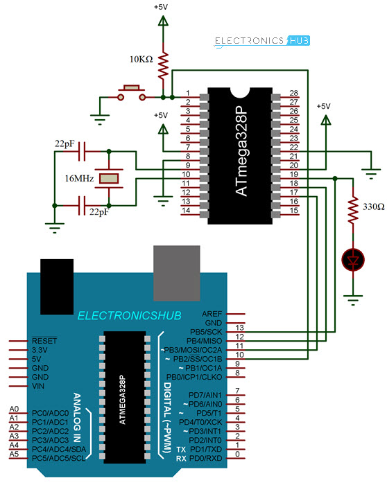
Circuit Diagram
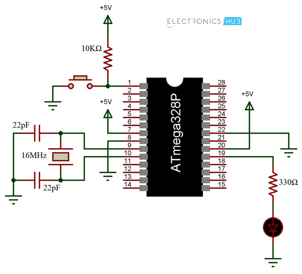
The circuit diagram for burning bootloader on ATmega328 Microcontroller using Arduino is shown below.
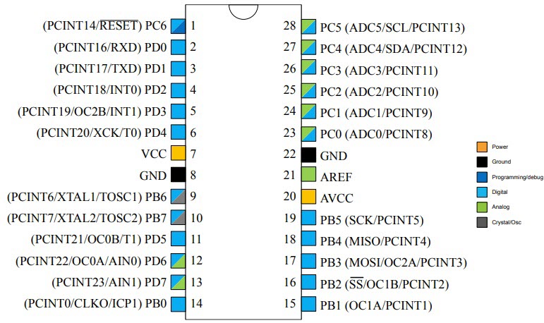
Pin diagram of the ATmega328 Microcontroller is shown in the following image, just in case.
Components Required
Arduino UNO
ATmega328 Microcontroller IC
16MHz Crystal
22pF x 2 Ceramic Capacitors
10KΩ Resistor
Push Button
330Ω Resistor
LED
Breadboard
Connecting Wires
5V Power Supply
Procedure for Programming Bootloader on Atmega328
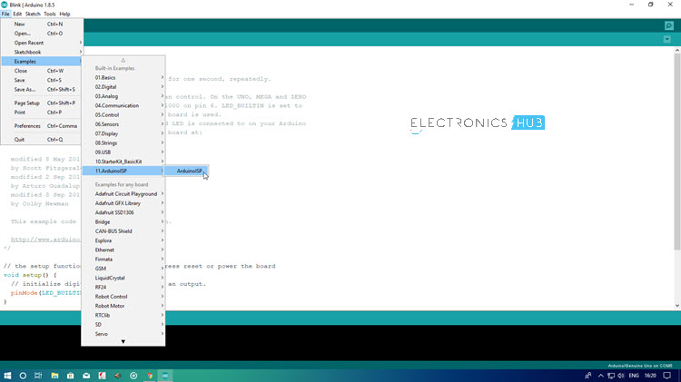
As mentioned earlier, Arduino UNO is being used as an AVR programmer here. In order to achieve that, you have to upload a special program onto your working Arduino UNO board called “Arduino ISP”.
So, before making the connections, connect the working Arduino UNO to the computer using USB cable and select the appropriate board and PORT in the Arduino IDE.
Now, go to File > Examples > ArduinoISP > ArduinoISP. Upload this code to you Arduino UNO in order to turn your Arduino UNO board into an AVRISP Programmer.
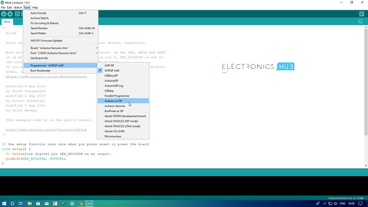
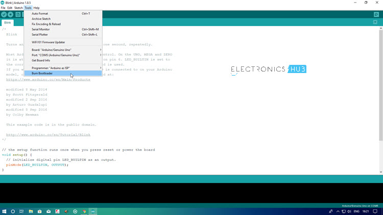
After completing this step, make the necessary connections (if not made already). Now go to Tools > Programmer and select “Arduino as ISP” option. After this, you are ready to burn the bootloader.
Simply, go to Tools and click on “Burn Bootloader”. Your target ATmega328 Microcontroller will be programmed with bootloader.
Upload Sketches to ATmega328
Once you are done with uploading the Bootloader on ATmega328 Microcontroller, you can continue further by uploading a test sketch on to it. For this, retain the same connections as earlier and open any sketch like Blink Sketch, for example.
Do not change any options i.e. the programmer is still set to “Arduino as ISP”. Now, by holding the “Shift” button on the keyboard, click on “Upload” icon. This will upload the sketch to the ATmega328 Microcontroller IC by using Arduino UNO as the programmer.
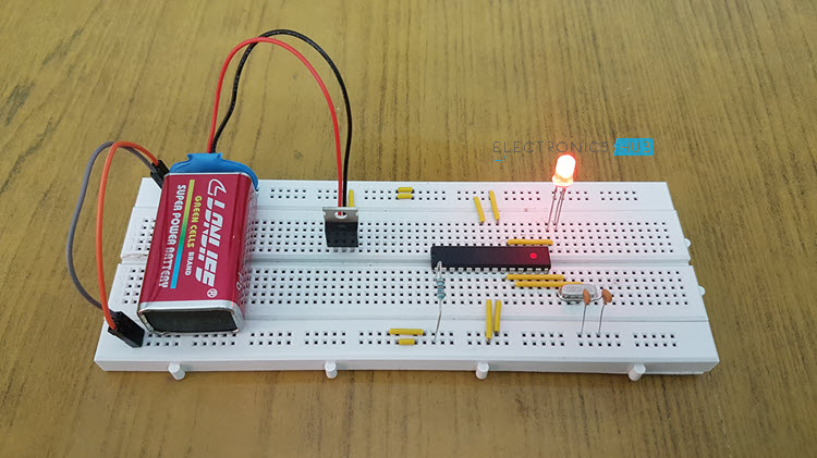
After completing this, you can disconnect the Arduino UNO from ATmega328 Microcontroller and use ATmega328 IC as a standalone device with Blink sketch running on it.
The following image shows the ATmega328 Microcontroller running Blink sketch after being uploaded with the help of Arduino UNO.
NOTE: In order to upload code to Arduino UNO, make sure to switch the programmer back to “AVRISP mkII”.
Conclusion
In this project, I have shown you how to burn Bootloader on ATmega328 Microcontroller IC and also as an extra option I have also shown you how to upload Arduino sketches onto ATmega328 with Bootloader using Arduino UNO.
In this project, I will show you how to build an Arduino Wattmeter, a device that can be used to measure the power consumed by a load. In addition to the Wattmeter, this circuit can also act as a Voltmeter and Ammeter to measure voltage and current.
Introduction
Measuring Voltage, Current and subsequently the Power is an essential task of any electronics engineer. For measuring voltage and current, you can use simple handheld multimeters as they provide both the range and accuracy for normal usage.
But in order to measure power, you have several options like simple wattmeters to complex power analyzers and power meters.
What if I told you that you can make your own Wattmeter with simple components as a DIY Project, which can be used in your LED or Solar related projects?
Instead of buying a readily available and an expensive Wattmeter, you can easily make your own Arduino Wattmeter. I will explain all necessary steps required for the same.
Concept of Arduino Wattmeter Project
There are number of ways that you can implement the Arduino Wattmeter Project. One of the easy ways is to interface a Voltage Sensor and a Current Sensor with Arduino, measure the voltage and current values and finally with some mathematics, you can calculate the Power in Watts.
Although using sensors can provide accurate results, where is the fun in using sensors if you can build the entire system yourself. This is beneficial if you are a student and trying to grab the underlying concepts.
The method which I will be implementing involves complete design of the circuit. For ease of understanding I will divide the circuit into two halves: The Sensor part and The Control Part.
The Sensor Part of the circuit is responsible for measuring the Voltage across the load and Current through the load. Both these values, which are analog in nature, are given to the Arduino to its ADC. Arduino converts these values to digital values and makes a few calculations as displays the results on the LCD.
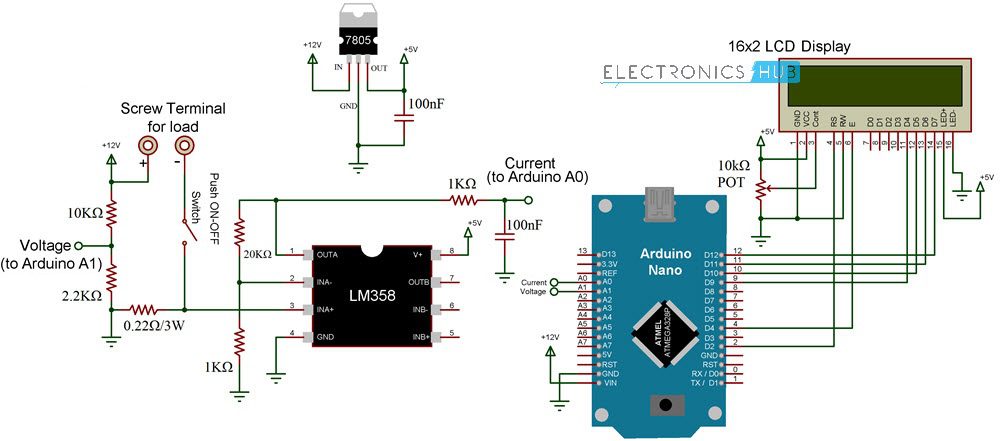
Circuit Diagram
The following image shows the circuit diagram of Arduino Wattmeter.
Components Required
Arduino UNO or Nano
16×2 LCD Display
LM358 Op Amp
7805 Voltage Regulator
Resistors – 0.22Ω/3W, 1KΩ x 2, 2.2KΩ, 10KΩ, 20KΩ
10KΩ Potentiometer
Capacitors – 100nF x 2 (0.1µF – Code 104)
Push ON – Push OFF Button
Connecting Wires
Terminals for connecting Load
12V Power Supply
Code
The code for project is given below.
Working of Arduino Wattmeter
In the sensor part of the circuit, there are two areas which are responsible for measuring voltage and current. For measuring the voltage, a voltage divider circuit is implemented using a 10KΩ and a 2.2KΩ Resistor.
Using these resistors, you can measure voltages up to 24V. These resistors also help us bringing the voltage range to 0V – 5V, which is the range Arduino works on.
Now, coming to the current measurement, Arduino or any Microcontroller for that matter can only accept analog voltage as input i.e. it can only read voltages. If Arduino can only read voltages, then how can we measure current?
In order to measure current, you have to convert the current values to appropriate voltage values. Here comes the Ohm’s Law to the rescue. As per Ohm’s Law, the voltage drop across a load is proportional to the current. Hence, a small shunt resistor is placed with respect to the load. By measuring the voltage across this resistor, you can measure the current.
The shunt resistor used here is of 0.22Ω (3W). Even when the load draws a current of 1A (which is the theoretical limit of this circuit and shouldn’t exceed this value), the voltage across the shunt resistor is only 0.2V.
This value is very low for Arduino’s ADC circuit. Hence, I have used LM358 Op Amp in Non-Inverting Amplifier Mode to amplify the values provided to Arduino. The voltage divider network for the feedback control consists of 20KΩ Resistor and 1KΩ Resistor. These resistors contribute to a gain of approximately 21.
Output of the Amplifier is filtered and given to Analog Input pin of Arduino. Arduino takes both the voltage and current (masked as voltage) values at Analog Input pins A1 and A0 respectively. After performing few calculations, it then displays the values of Voltage, Current and Power on the LCD Display.
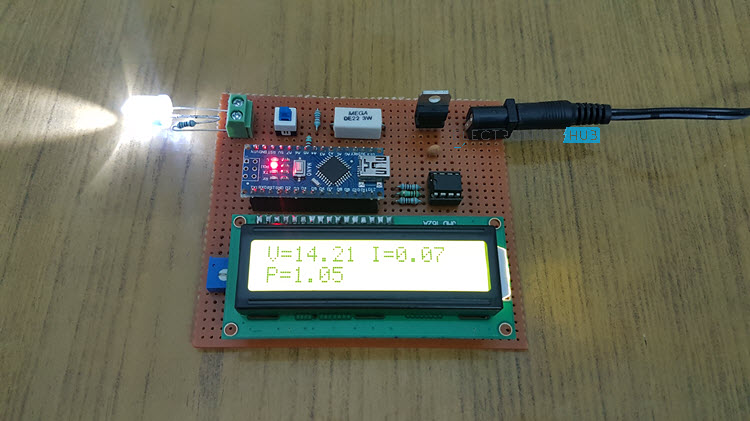
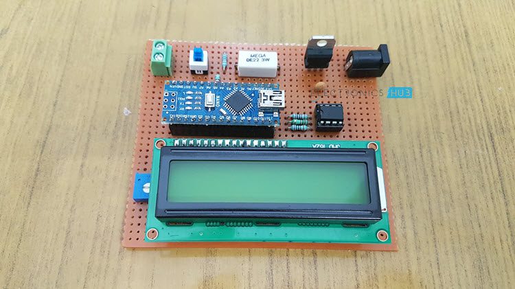
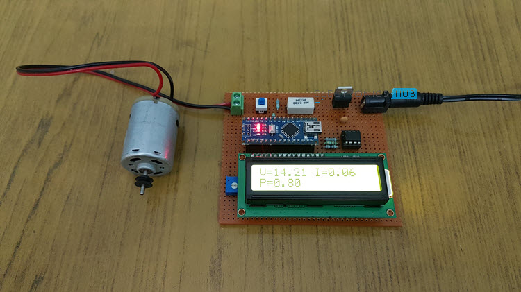
Testing Arduino Wattmeter Circuit
After designing the circuit on a perf board and making all the necessary connections, I have used the circuit to test a couple of loads like LED and a Motor. I have used a 12V Power supply and all the results are satisfactory.
Conclusion
A simple Arduino Wattmeter is designed in this project with the aim of measuring power consumed by small loads (up to 12W). In a future implementation, as an extension to this project, I will design a new circuit based on Voltage and Current Sensors for more accurate results.
In this fun DIY project, I will show you how to make an Arduino based Piano. It is a simple project made using Arduino UNO, few push buttons and a Piezo Buzzer. A special feature of this project is that Arduino will record the last played set of tones and repeat those tones like a one time record and repeat feature.
To keep things simple, I haven’t used any display (like 16×2 LCD Display).
Introduction
We have seen some application oriented projects using Arduino like Heart Rate Monitor, Robotic Arm, Home Automation, etc. Sometimes, we make projects just for fun like 8x8x8 LED Cube, Hand Gesture Control of Computer, etc.
The Arduino based Piano project comes under the category of fun projects as you know, this project doesn’t have any real world applications (at least not directly) but can be used to understand certain features of Arduino (like its sound producing capabilities using the tone () function).
None the less, sounds and tones can provide a great audio feedback in our projects.
How to make Arduino based Piano?
Instead of asking how to make an Arduino based Piano, the correct question should be how to generate different tones using Arduino. We know that Arduino is capable of producing PWM signals.
I will be using this feature of Arduino to generate tones. The other way to generate tones using Arduino is to use the function tone () function.
Using tone () function, you can generate square waves of different frequencies but with fixed duty cycle (50%). Internally, the tone () function relies on the Timers of Arduino (or the ATmega328P Microcontroller, to be more accurate).
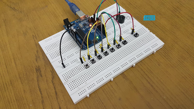
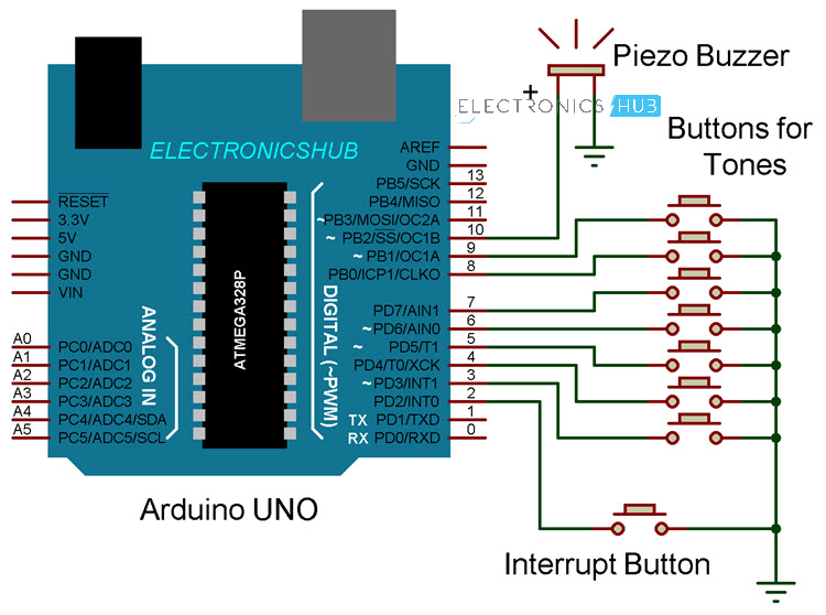
Circuit Diagram
The following image shows the circuit diagram for piano application using Arduino. As you can see from the circuit diagram, it is a fairly simple circuit.
Components Required
Arduino UNO
Push Buttons X 8
Small Piezo Buzzer (or a small speaker)
Connecting Wires
Breadboard
Power Supply
Circuit Design
The design of Arduino Piano circuit is very easy. First, connect a 5V Piezo Buzzer i.e. its positive terminal to Pin 10 of Arduino. It is necessary that you connect the Piezo Buzzer to one of the PWM capable pins of Arduino. The other end of the Piezo Buzzer is connected to GND.
Now, connect 7 Push Buttons to digital I/O pins 3 through 9 of Arduino. These pins act as the tone input pins. I have used the INTERNAL PULL UP feature of Arduino and hence I haven’t connected any external pull-up resistors to these pins.
All the other terminals of these push buttons are connected to GND. Finally, another push button is connected to Pin 2 of Arduino to act as an Interrupt pin. The other end of this button is also connected to GND.
I have used the on-board LED (LED connected to Pin 13) to indicate between regular tone play and recorded tone play.
Code
The code for the project How to make Arduino based Piano is given below.
Working
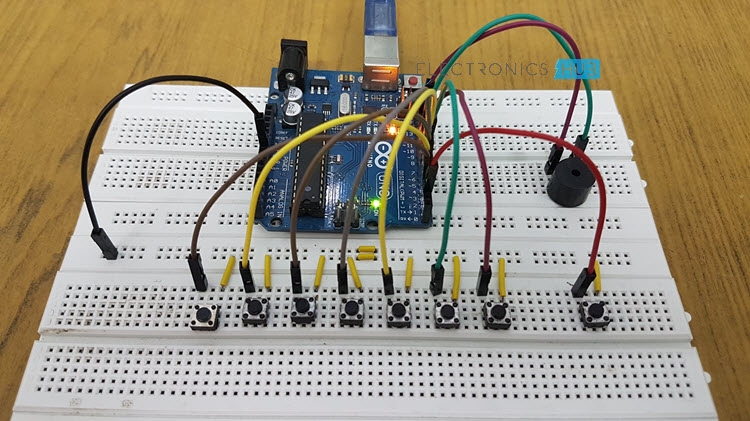
Make the connections as per the circuit diagram and upload the code to Arduino. Once the power to the circuit is turned on, Arduino is ready to accept the input from the buttons.
Each button is associated with a PWM signal in the code. When a button is pushed, that particular PWM signal is generated through the Piezo Electric Buzzer.
Now for the record and repeat mode, play a few tones using different buttons. With each button pressed, Arduino starts recording i.e. makes note of the sequence of the buttons, its on time and off time.
Once you are done with the tone, you can push the Interrupt Button. As soon as the Arduino enters Interrupt Mode, all the previously pressed tones are played back through the Piezo Buzzer.
During normal tone playback i.e. when the buttons are being pressed, the LED on pin 13 stays ON. During repeat mode, it stays OFF.
An important point to understand here is that I did not use the tone() function of Arduino. You can try to generate sounds of different frequencies using that function.
Conclusion
A fun DIY Project called Arduino based Piano is implemented here. This project can be helpful in understanding the sound capabilities of Arduino. Although I haven’t used the tone () function, you can implement the same using that function for more accurate results.
Download Project Document/Synopsis Nowadays Women Safety is the biggest concern in many parts of the world. There is still a fear in alone areas for women as well as men. So here we propose a security patrolling robot using Raspberry PI. The system uses cameras and mic mounted on robotic vehicle for securing any premises. […]
Download Project Document/Synopsis This is the mini project designed to control Plant watering using a standard TV remote. IR sensor is interfaced to the control unit for sensing the IR signals transmitted by the remote. This data is conveyed to the control unit which switches the DC water Pump on or off as desired. An […]
Here I show you all uses Zener Diodes voltage Rating table for Part no to voltage calculation.
1N4728A 3.3 V
1N4729A 3.6 V
1N4730A 3.9 V
1N4731A 4.3 V
1N4732A 4.7 V
1N4733A 5.1 V
1N4734A 5.6 V
1N4735A 6.2 V
1N4736A 6.8 V
1N4737A 7.5 V
1N4738A 8.2 V
1N4739A 9.1 V
1N4740A 10 V
1N4741A 11 V
1N4742A 12 V
1N4743A 13V
1N4744A 15 V
1N4745A 16 V
1N4746A 18 V
1N4747A 20 V
1N4748A 22 V
1N4749A 24 V
1N4750A 27 V
1N4751A 30 V
1N4752A 33 V
1N4753A 36 V
1N4754A 39 V
1N4755A 43V
1N4756A 47 V
1N4757A 51 V
1N4758A 56 V
1N4759A 62 V
1N4760A 68 V
1N4761A 75 V
1N4762A 82 V
1N4763A 91 V
1N4764A 100 V
zener diode image operation of zener diode zener diode discussion zener diode as switch types of zener diode physics zener diode zener diode number zener diode in parallel zener diode code list zener diode code pdf zener diode codecalculator zener diode codelist pdf zener diodevalue chart how to identifyzener diodevalue zener diodenumber list zener diodemarkingcode
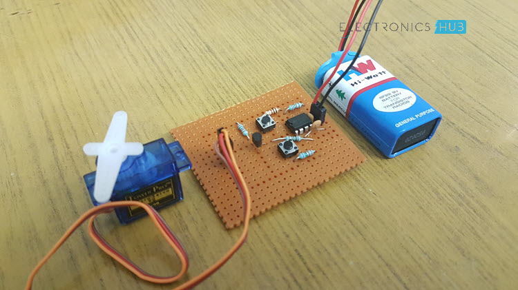
In this DIY project, I will show you how to make a Simple Servo Motor Tester Circuit and how to use circuit in order to check whether your servo motor is working properly or not.
Introduction
When it comes to hobby projects and beginner electronics projects, Servo Motors are one of the important devices that we often use. Servo Motors are the main work horses in a variety of projects like Solar Tracker, Robotic Arm, Obstacle Avoiding Robot and many other small as well as complex projects.
When using Servo motors in your projects, you might have faced issues like the servo motor not working properly or doesn’t provide complete (possible) rotation. In situations like these, a simple Servo Motor Tester Circuit will be helpful.
A Servo Motor Tester is a simple circuit designed specifically for testing the functionality of a Servo Motor. You can also use this circuit to test a newly bought Servo Motor to check if it is a faulty one.
NOTE: Even though Servo Motors are a huge part several industrial and automations applications, I am limiting my discussion of this project to Servo Motors like TowerPro SG90 (Plastic Gears) and TowerPro MG90S (Metal Gears), which are often used in hobby and DIY projects.
How to make a Simple Servo Motor Tester Circuit?
In order to design a simple Servo Motor Tester Circuit, you need to first understand how a servo motor works. I won’t go into minute details of how a servo motor works but give a general idea.
Basically, a Servo Motor works on the principle of pulse width modulation or PWM. The angle of rotation of the servo motor is controlled by the PWM Signal applied to the Pulse Pin (or Control Pin) of the servo motor (usually, the Orange wire).
To be more specific, the duration of the pulse provided to the Control Pin will decide the angle of rotation of the servo. We know that most of the servo motors available today can be rotated from 0 degrees to 180 degrees. When the duration of the pulse is 1 milli second (1 ms), the shaft of the servo is rotated to 0 degrees.
If the duration is increased to 1.5 milli seconds (1.5 ms), the servo rotates to 90 degrees. This is the default position. When the duration of the pulse is further increased to 2 milli seconds (2 ms), the servo rotates all the way to 180 degrees.
So, in order to make and design a Servo Motor Tester circuit, you need to generate a PWM Signal and also control the duration of the pulse. In order to generate the PWM or Pulse Width Modulated Signal, I have used the good old reliable 555 Timer IC.
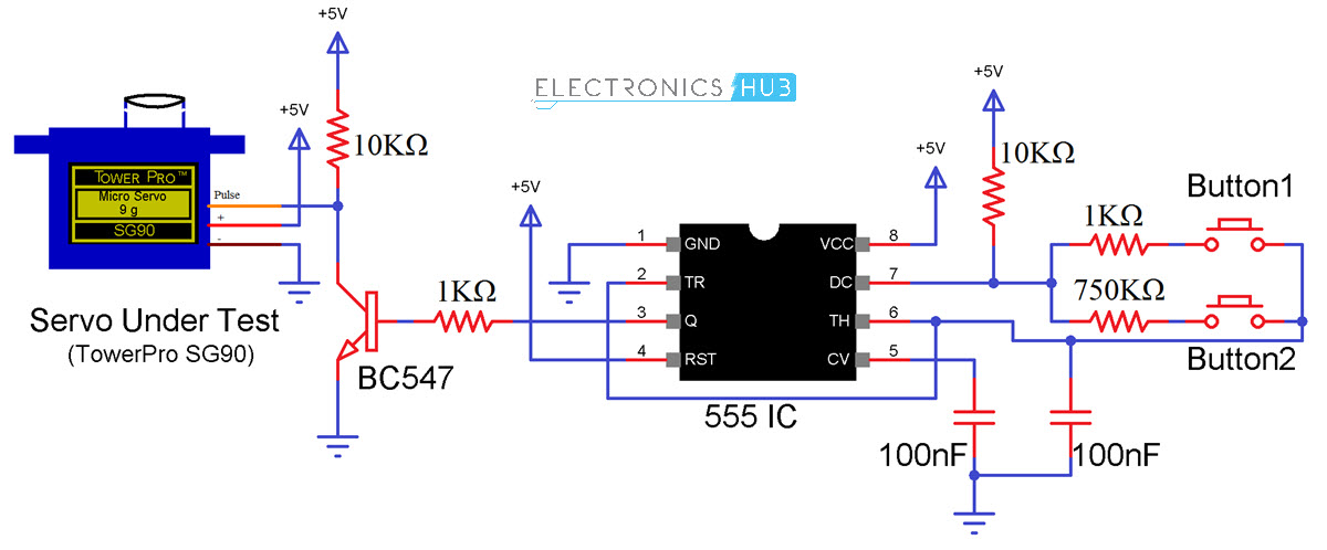
Circuit Diagram of Servo Motor Tester
Components Required
555 Timer IC
Servo Motor under Test (like SG90 or MG90S from TowerPro)
Push Buttons X 2
10KΩ Resistors X 2
10Ω Resistors X 2
750KΩ Resistor (* for info in circuit design)
100nF Capacitors X 2
Perf Board or Breadboard
How to Design Servo Motor Tester Circuit?
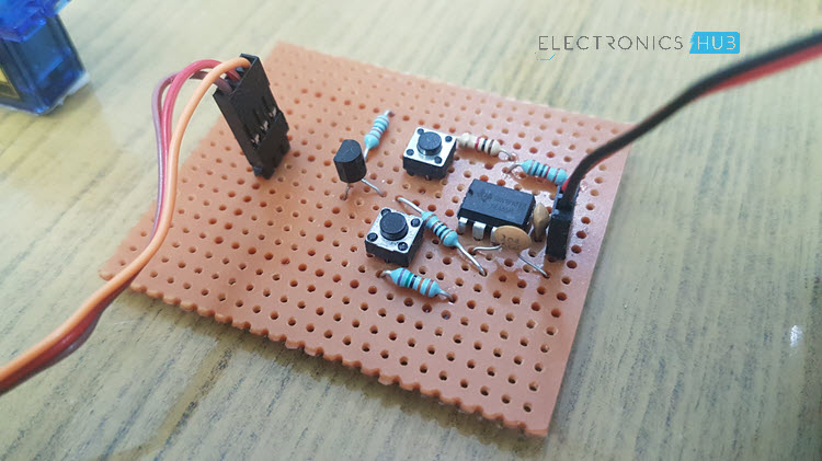
First, connect the Pins 8 and 4 (VCC and RST) of the 555 Timer IC to +5V supply and connect the Pin 1 (GND) to ground. Short Pins 2 and 6 (TR and TH) and connect a 100nF Capacitor between Pin 6 and GND and another 100nF Capacitor between Pin 5 (CV) and GND.
Now, connect a 10KΩ Resistor between Pin 7 (DIS) and +5V. Now comes the tricky part. Connect two Resistors of 1KΩ and 750KΩ between Pin 7 and 6 through individual Push Buttons as shown in the circuit diagram.
The choice of 750KΩ Resistor is not mandatory. Theoretically, a 12K resistor will produce the necessary 2ms pulse but practically, I did not get that value. So, with a lot of trial and error setup, I got satisfactory results with 750KΩ. Your circuit may not be the same. So, I suggest starting with 12K and gradually increasing with all the other value same until you get the result.
Now, the output of the 555 Timer IC i.e. the Pin 3 (OUT) is connected to an NPN Transistor (BC547) through a current limiting 1KΩ Resistor. The emitter terminal is connected to GND and the Collector terminal is connected to the Pulse pin of the servo motor as well as a 10KΩ Pull-up resistor.
Working
The working of this Simple Servo Motor Tester Circuit can be easily understood if you are familiar with the working of 555 Timer IC in Astable Multivibrator operation. 555 Timer IC is configured to operate in Astable Mode i.e. Square Wave mode.
In this mode, the width of the pulse can be modified by varying the values of resistor R2 i.e. the resistor between Pin 7 and 6. So, I have used to resistors with two push buttons. When the first button is pressed, 1KΩ Resistor is connected and the pulse duration is 1ms. This makes the servo to rotate to 0 degree.
When I press the second button, the other resistor (in my case 750KΩ) is connected and will generate a 2ms pulse duration. Hence, the servo will rotate to 180 degrees.
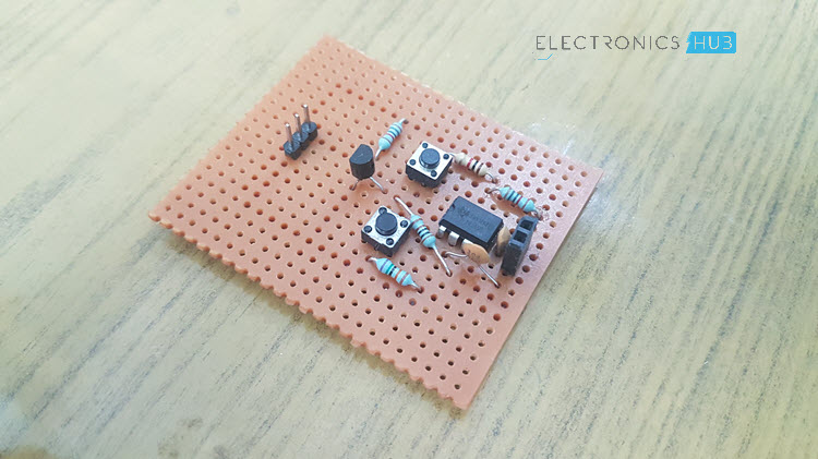
Conclusion
A simple but efficient Servo Motor Tester Circuit is designed in this project, which can be used to test the working small servo motors like TowerPro SG90 or TowerPro MG90S.
In this project, I will talk about Shift Registers, one of the popular Shift Register ICs – 74HC595 and finally how to use the 74HC595 Shift Register with Arduino and the benefits of this interface.
Introduction
Normally, consider a small application where you want to drive 8 LEDs with the help of Arduino (or any microcontroller). This application, though a very basic and simple one, would require you to use 8 of the available Input / Output Pins of your Arduino Board: one for each LED.
Now consider a slightly advanced project, where your requirements are driving the same 8 LEDs and also doing other stuff like displaying a message or any information on a 16×2 LCD Display or interface a Bluetooth Device to control the LEDs through a smart phone!!!
This type of bigger projects would consume a lot of your I/O Pins on your Arduino Board and there might not be enough pins left for interfacing additional devices.
Here comes the Shift Register IC to the rescue.
What is a Shift Register?
A Shift Register is basically a Serial-to-Parallel Converter IC. It basically takes a serial input through a single pin (well, technically you need at least 3 pins, which I will talk about later) and converts it into 8-bit parallel output thus effectively reducing the number of interface pins between a Microcontroller and its output devices.
There are other flavours of shift registers like Serial IN Parallel OUT (the one we are interested in), Serial IN Serial OUT, Parallel IN Serial OUT and Parallel IN Parallel OUT. For more information on Shift Registers, visit SHIFT REGISTERS TYPES AND APPLICATIONS.
In this project, I will be using a Serial IN and Parallel OUT type Shift Register IC called 74HC595.
A Brief Note 74HC595 Shift Register IC
As mentioned earlier, the 74HC595 IC is an 8-bit Serial IN Parallel OUT shift register. It is 16-pin IC available in a wide range of packages like DIP, SOIC, SSOP and TSSOP.
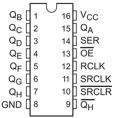
Pin Diagram of 74HC595 Shift Register
The following image shows the Pin Diagram of 74HC595 Shift Register.
Pin Description of 74HC595 Shift Register
Following table describes the pins of 74HC595 Shift Register in brief.
Pin Number
Pin Name
Description
15, 1-7
QA, QB – QH
QA – QH (8) Output Pins
8
GND
Ground Pin
9
QH’
QH’ Output
10
SRCLR’
Reset Input
11
SRCLK
Clock Input
12
RCLK
Storage Register Clock Input
13
OE’
Output Enable
14
SER
Serial Input
16
VCC
Supply Voltage
NOTE: There are several manufacturers of 74HC595 Shift Register IC and the naming convention of each manufacturer may be different. Check out the data sheet based on the manufacturer. The above pin names are from the data sheet provided by Texas Instruments.
How to use 74HC595 Shift Register with Arduino?
Let me build a simple circuit where I will use only three pins of Arduino UNO and control 8 LEDs. This will be possible by using the 74HC595 Shift Register with Arduino.
The three pins of the shift register that are needed to be connected to Arduino are pins 11 (the clock input), 12 (the storage register clock input or simply the latch input) and 14 (the data input).
All the 8 LEDs will be connected to the shift register IC. (more details in the circuit design section).
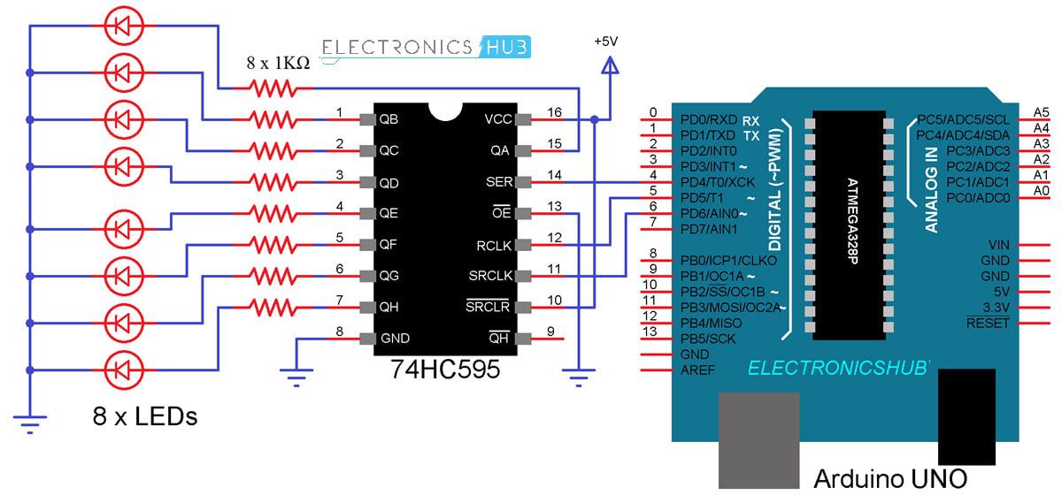
Circuit Diagram
The following image shows the circuit diagram of interfacing 74HC595 Shift Register with Arduino UNO.
Components Required
Arduino UNO
74HC595 Shift Register IC
Breadboard
8 X LEDs
8 X 1KΩ Resistors
5V Power Supply
Connecting Wires
Circuit Design
First, connect the Serial Input Pin of 74HC595 Shift Register to Pin 4 of Arduino. Then connect the clock and latch pins i.e. pins 11 and 12 of 74HC595 to pins 6 and 5 of Arduino respectively.
Now, connect 8 LEDs with individual current limiting 1KΩ Resistors to the 8 output pins of 74HC595 IC. Coming to the power supply, connect a separate 5V power supply to 74HC595 IC with common GND to Arduino rather than supplying 5V from Arduino.
Code
The following is a simple code for turning the LEDs ON in a sequence.
Working
Let us now try to understand the working of this project. Initially, all the LEDs will be OFF as the byte variable LED is set to 0. Now, each bit is set to 1 using the “bitSet” function and is shifted out using the “shiftOut” function.
Correspondingly, each LED will be turned on in the same sequence. If you want to turn the LED off, you can use the “bitClear” function.
Applications
The 74HC595 Shift Register IC or any similar shift register for that matter can be used in the following applications:
The IoT is developing at a rapid pace, and so is the need for small, inexpensive computing hardware. An IoT board must incorporate advanced functionalities in a tiny package. The Internet of Things (IoT) has been described as the fourth industrial revolution by design engineers. It has changed the way we live, by way of […]
In this tutorial we will learn how to make an Arduino Robot Arm which can be wirelessly controlled and programmed using a custom-build Android application. I will show you the entire process of building it, starting from designing and 3D printing the robot parts, connecting the electronic components and programming the Arduino, to developing our own Android application for controlling the Robot Arm.
Overview
Using the sliders in the app we can manually control the movement each servo or axis of the robot arm. Also using the “Save” button we can record each position or step and then the robot arm can automatically run and repeat these steps. With the same button we can pause the automatic operation as well as reset or delete all steps so that we can record new ones.
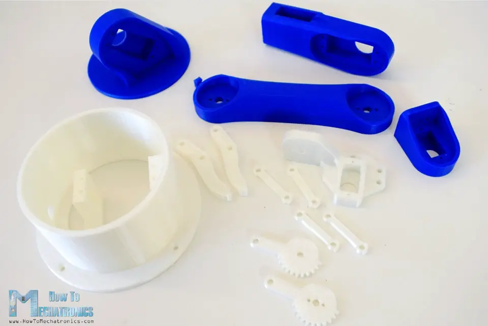
Arduino Robot Arm 3D Model
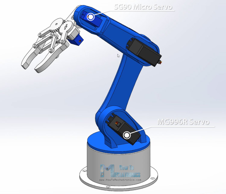
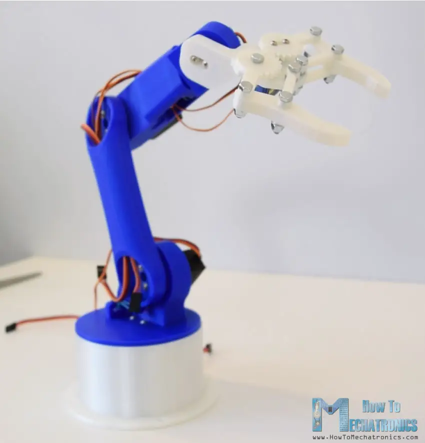
To begin with, I designed the Robot Arm using Solidworks 3D modeling software. The arm has 5 degrees of freedom.
For the first 3 axis, the waist, the shoulder and the elbow, I used the MG996R servos, and for the other 2 axis, the wrist roll and wrist pitch, as well as the gripper I used the smaller SG90 micro servos.
You can download and the 3D model below.
Solidworks:
Arduino Robot Arm 3D Model Solidworks Files 5.14 MB
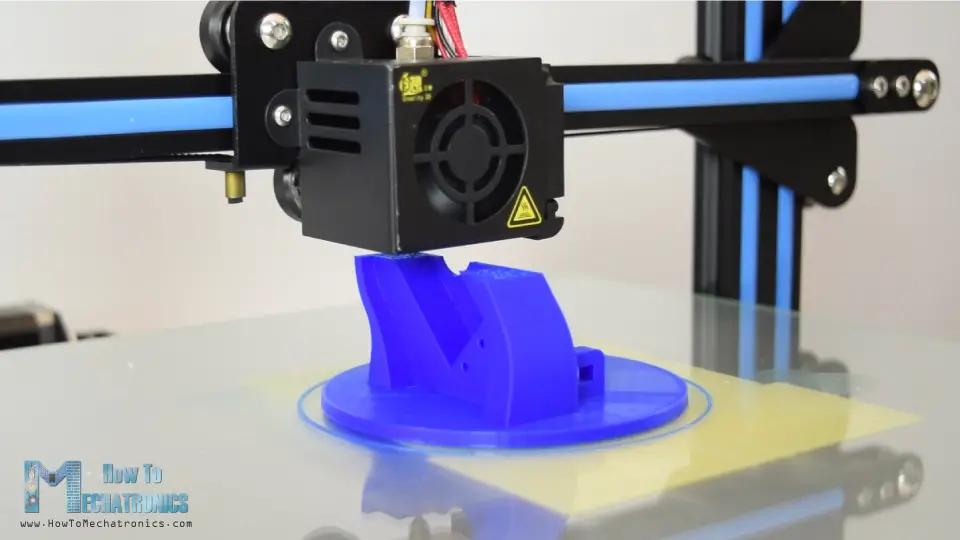
Using my new 3D Printer, Creality CR-10, I 3D printed all of the parts for the Arduino robot arm.
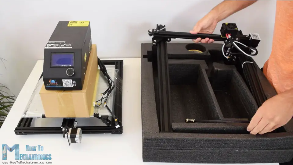
Here I would like to give a shout-out to Banggood.com for providing me this awesome 3D printer. The Creality CR-10 printing quality is amazing for its price point and what’s also great about it is that it comes almost 90% pre-assembled.
In order to complete the assembly we just have to connect the upper and lower parts frames using some bolts and brackets, and then connect the electronic components with the control box using the provided cables.
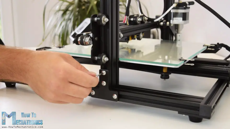
Before trying it, it is recommended check whether the roller wheels are tight enough, and if they are not, you can simply use the eccentric nuts to tight them up. And that’s it, after leveling your 3D printing bed, you are ready to transform your 3D creations into reality. I had all of the parts for the Arduino Robot Arm ready in just several hours.
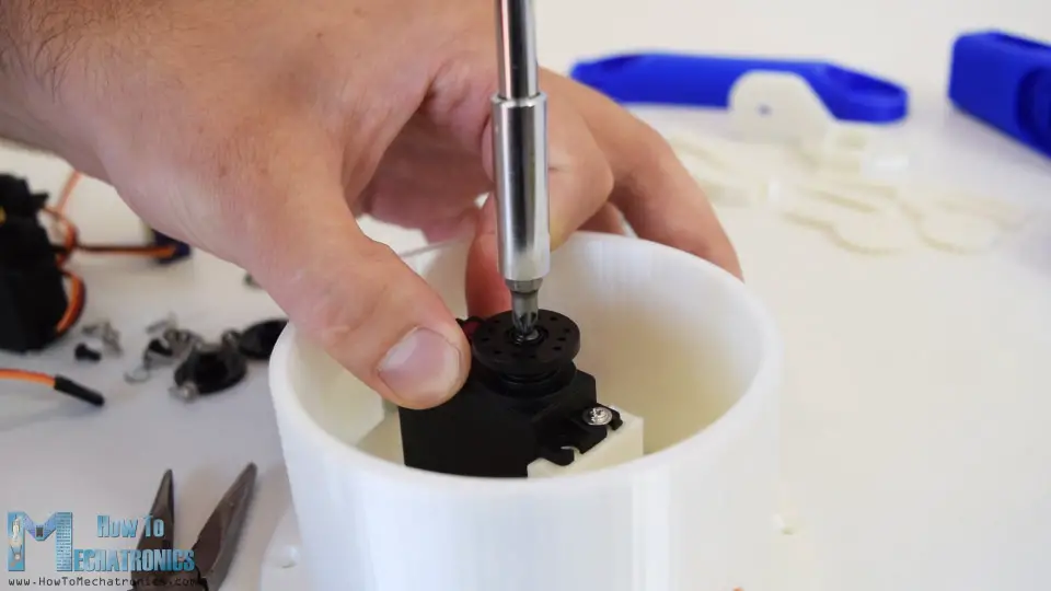
Assembling the Robot Arm
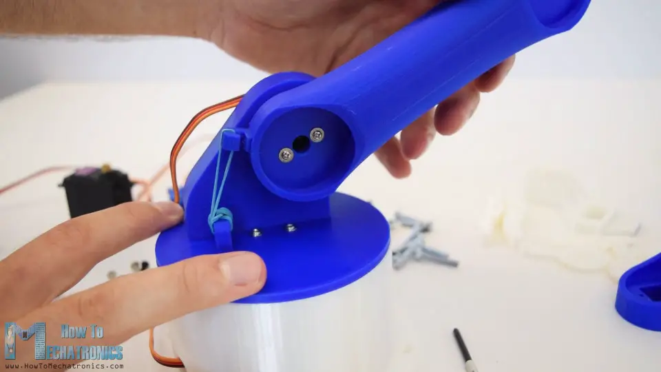
Ok, so at this point we are ready to assemble the robot arm. I started with the base on which I attached the first servo motor using the screws included in its package. Then on the output shaft of the servo I secured a round horn a bolt.
And on top of it I placed the upper part and secured it using two screws.
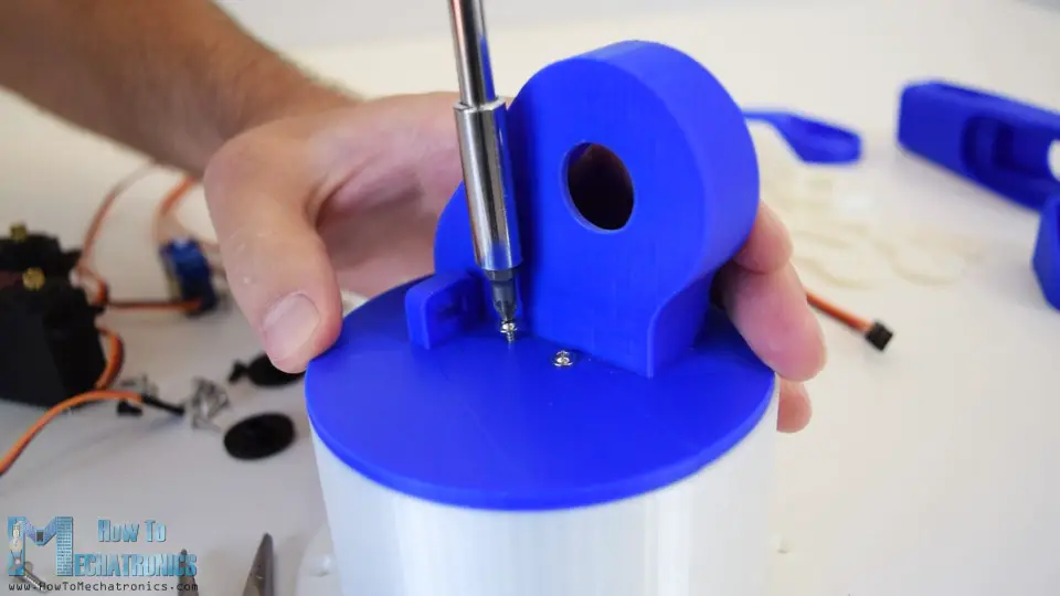
Here again first goes servo, then the round horn onto the next part, and then they are secured to each other using the bolt on the output shaft.
We can notice here that at the shoulder axis it is good idea to include some kind of spring or in my case I used a rubber band to give some help to the servo because this servo carries the whole weight of the rest of the arm as well as the payload.
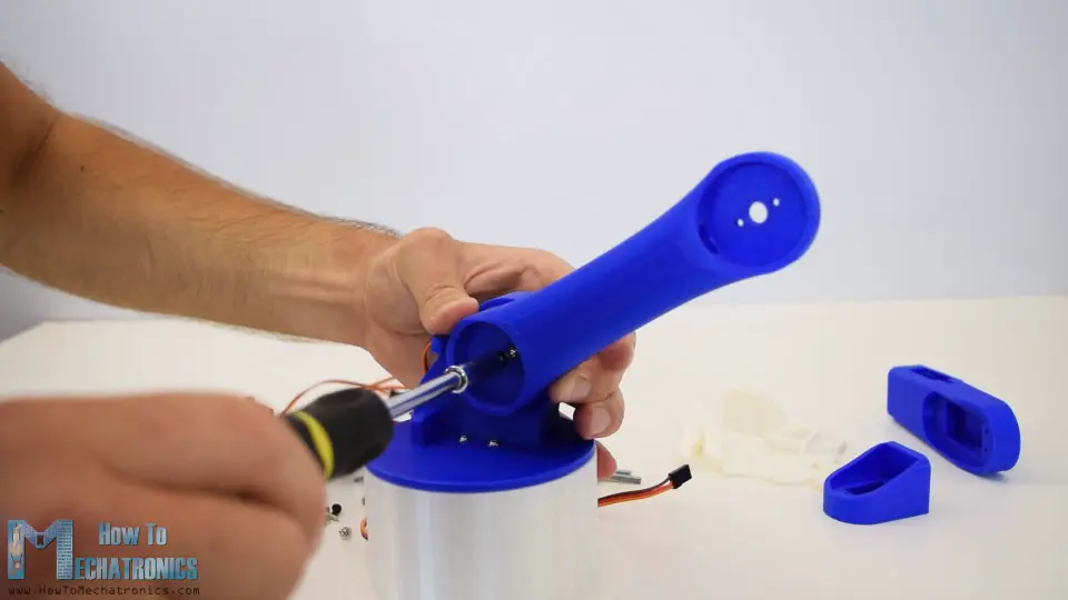
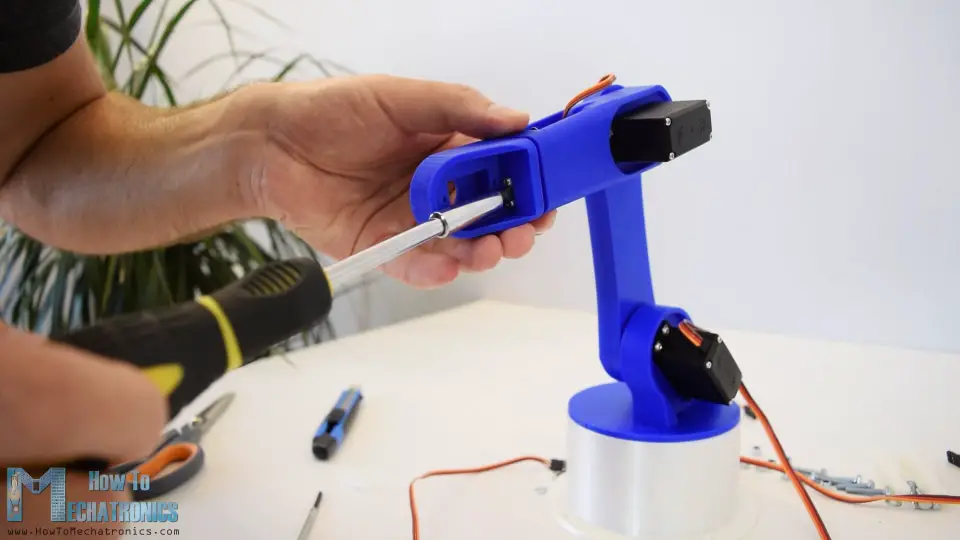
In similar way I continued to assemble the rest of the robot arm. As for the gripper mechanism I used some 4 millimeters bolts and nuts to assembly it.
Finally I attached the gripper mechanism onto the last servo and the Arduino robot arm was completed.
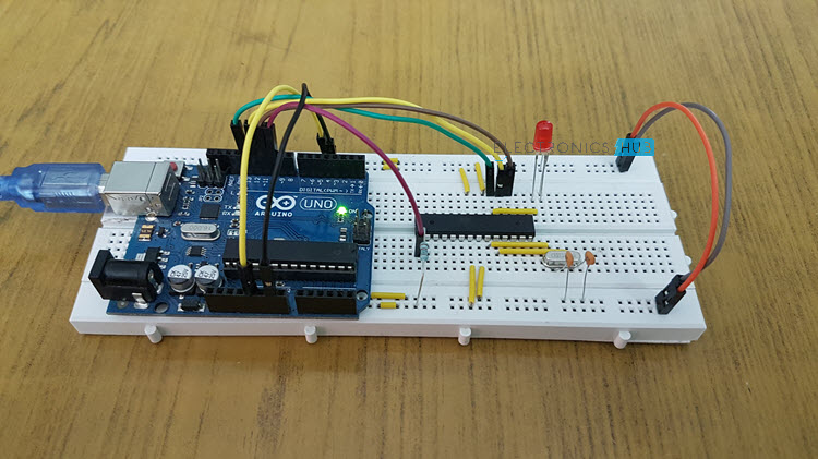
Arduino Robot Arm Circuit Diagram
The next stage is connecting the electronics. The circuit diagram of this project is actually quite simple. We just need an Arduino board and a HC-05 Bluetooth module for communication with the smartphone. The control pins of the six servo motors are connected to six digital pins of the Arduino board.
For powering the servos we need 5V, but this must come from an external power source because the Arduino is not able to handle the amount of current that all of them can draw. The power source must be able to handle at least 2A of current. So once we have connected everything together we can move on to programing the Arduino and make the Android app.
You can get the components needed for this example from the links below:
*Please note: These are affiliate links. I may make a commission if you buy the components through these links. I would appreciate your support in this way!
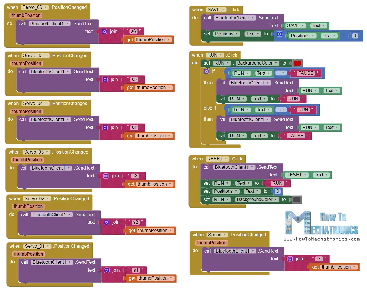
Arduino Robot Arm Code
As the code is a bit longer, for better understanding, I will post the source code of the program in sections with description for each section. And at the end of this article I will post the complete source code.
So first we need to include the SoftwareSerial library for the serial communication of the Bluetooth module as well as the servo library. Both of these libraries are included with the Arduino IDE so you don’t have to install them externally. Then we need to define the six servos, the HC-05 Bluetooth module and some variables for storing the current and previous position of the servos, as well as arrays for storing the positions or the steps for the automatic mode.
#include <SoftwareSerial.h>
#include <Servo.h>

Servo servo01;
Servo servo02;
Servo servo03;
Servo servo04;
Servo servo05;
Servo servo06;

SoftwareSerial Bluetooth(3, 4); // Arduino(RX, TX) - HC-05 Bluetooth (TX, RX)

int servo1Pos, servo2Pos, servo3Pos, servo4Pos, servo5Pos, servo6Pos; // current position
int servo1PPos, servo2PPos, servo3PPos, servo4PPos, servo5PPos, servo6PPos; // previous position
int servo01SP[50], servo02SP[50], servo03SP[50], servo04SP[50], servo05SP[50], servo06SP[50]; // for storing positions/steps
int speedDelay = 20;
int index = 0;
String dataIn = "";
In the setup section we need to initialize the servos and the Bluetooth module and move the robot arm to its initial position. We do that using the write() function which simply moves the servo to any position from 0 to 180 degrees.
void setup() {
  servo01.attach(5);
  servo02.attach(6);
  servo03.attach(7);
  servo04.attach(8);
  servo05.attach(9);
  servo06.attach(10);
  Bluetooth.begin(38400); // Default baud rate of the Bluetooth module
  Bluetooth.setTimeout(1);
  delay(20);
  // Robot arm initial position
  servo1PPos = 90;
  servo01.write(servo1PPos);
  servo2PPos = 150;
  servo02.write(servo2PPos);
  servo3PPos = 35;
  servo03.write(servo3PPos);
  servo4PPos = 140;
  servo04.write(servo4PPos);
  servo5PPos = 85;
  servo05.write(servo5PPos);
  servo6PPos = 80;
  servo06.write(servo6PPos);
}
Next, in the loop section, using the Bluetooth.available() function , we constantly check whether there is any incoming data from the Smartphone. If true, using the readString() function we read the data as string an store it into the dataIn variable. Depending on the arrived data we will tell robot arm what to do.
// Check for incoming data
  if (Bluetooth.available() > 0) {
    dataIn = Bluetooth.readString();  // Read the data as string
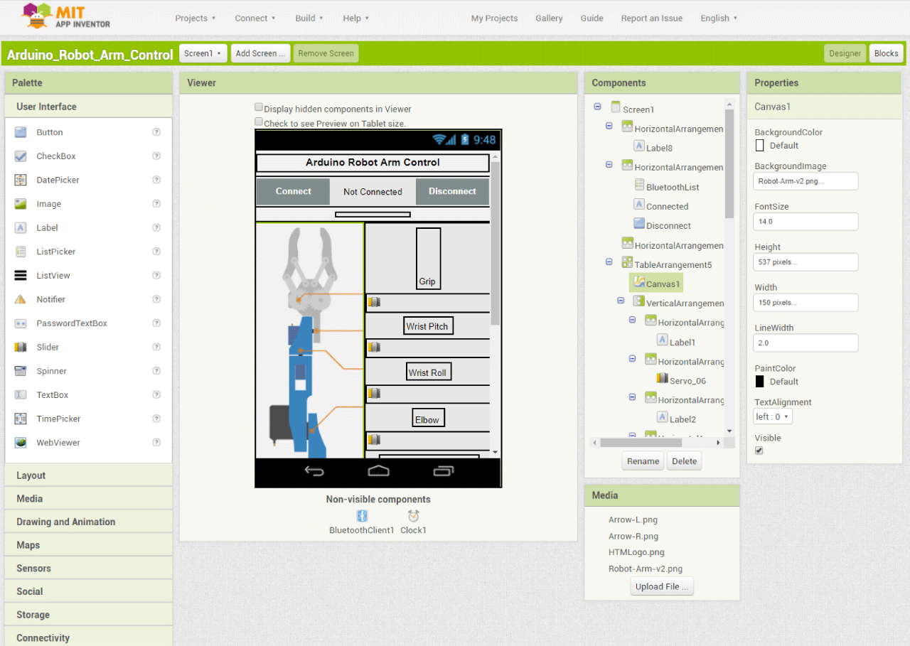
Arduino Robot Arm Control Android App
Let’s take a look at the Android app now and see what kind of data it is actually sending to the Arduino.
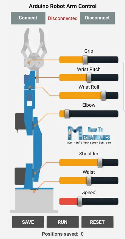
I made the app using the MIT App Inventor online application and here’s how it works. At the top we have two buttons for connecting the smartphone to the HC-05 Bluetooth module. Then on the left side we have an image of the robot arm, and on the right side we have the six slider for controlling the servos and one slider for the speed control.
Each slider have different initial, minimum and maximum value that suits the robot arm joints. At the bottom of the app, we have three button, SAVE, RUN and RESET through which we can program the robot arm to run automatically. There is also a label below which shows the number of steps we have saved. Nevertheless, for more details how to build apps like this using the MIT App Inventor you can check my other detailed tutorial for it.
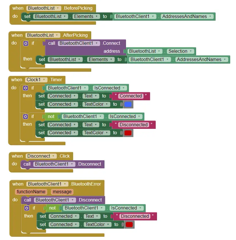
Ok, now let’s see the program or the blocks behind the application. First, on the left side we have the blocks for connecting the smartphone to the Bluetooth module.
Then we have the sliders blocks for the servo position control and the buttons blocks for programing the robot arm. So if we change the position of the slider, using the Bluetooth function .SendText, we send a text to the Arduino. This text consist of a prefix which indicates which slider has been changed as well as the current value of the slider.
So therefore, at the Arduino, using the startsWith() function we check the prefix of each incoming data and so we know what do to next. For example, if the prefix is “s1” we know that we need to move the servo number one. Using the substring() function we get the remaining text, or that’s the position value, we convert it into integer and use the value to move the servo to that position.
// If "Waist" slider has changed value - Move Servo 1 to position
    if (dataIn.startsWith("s1")) {
      String dataInS = dataIn.substring(2, dataIn.length()); // Extract only the number. E.g. from "s1120" to "120"
      servo1Pos = dataInS.toInt();  // Convert the string into integer
Here we can simply call the write() function and the servo will go to that position, but in that way the servo would run at its maximum speed which is too much for the robot arm. Instead we need to control the speed of the servos so I used some FOR loops in order to gradually move the servo from the previous to the current position by implementing a delay time between each iteration. By changing the delay time you can change the speed of the servo.
// We use for loops so we can control the speed of the servo
      // If previous position is bigger then current position
      if (servo1PPos > servo1Pos) {
        for ( int j = servo1PPos; j >= servo1Pos; j--) {   // Run servo down
          servo01.write(j);
          delay(20);    // defines the speed at which the servo rotates
        }
      }
      // If previous position is smaller then current position
      if (servo1PPos < servo1Pos) {
        for ( int j = servo1PPos; j <= servo1Pos; j++) {   // Run servo up
          servo01.write(j);
          delay(20);
        }
      }
      servo1PPos = servo1Pos;   // set current position as previous position
    }
The same method is used for driving each axis of the robot arm.
Below them is the SAVE button. If we press the SAVE button, the position of each servo motor is stored in an array. With each pressing the index increases so the array is filled step by step.
// If button "SAVE" is pressed
    if (dataIn.startsWith("SAVE")) {
      servo01SP[index] = servo1PPos;  // save position into the array
      servo02SP[index] = servo2PPos;
      servo03SP[index] = servo3PPos;
      servo04SP[index] = servo4PPos;
      servo05SP[index] = servo5PPos;
      servo06SP[index] = servo6PPos;
      index++;                        // Increase the array index
    }
Then if we press the RUN button we call the runservo() custom function which runs stored steps. Let’s take a look at this function. So here we run the stored steps over and over again until we press the RESET button. Using the FOR loop we run through all positions stored in the arrays and at the same time we check whether we have any incoming data from the smartphone. This data can be the RUN/PAUSE button, which pauses the robot, and if clicked again continues with the automatic movements. Also if we change the speed slider position, we will use that value to change the delay time between each iteration in the FOR loops below, which controls the speed of the servo motors.
// Automatic mode custom function - run the saved steps
void runservo() {
  while (dataIn != "RESET") {   // Run the steps over and over again until "RESET" button is pressed
    for (int i = 0; i <= index - 2; i++) {  // Run through all steps(index)
      if (Bluetooth.available() > 0) {      // Check for incomding data
        dataIn = Bluetooth.readString();
        if ( dataIn == "PAUSE") {           // If button "PAUSE" is pressed
          while (dataIn != "RUN") {         // Wait until "RUN" is pressed again
            if (Bluetooth.available() > 0) {
              dataIn = Bluetooth.readString();
              if ( dataIn == "RESET") {
                break;
              }
            }
          }
        }
        // If SPEED slider is changed
        if (dataIn.startsWith("ss")) {
          String dataInS = dataIn.substring(2, dataIn.length());
          speedDelay = dataInS.toInt(); // Change servo speed (delay time)
        }
      }
      // Servo 1
      if (servo01SP[i] == servo01SP[i + 1]) {
      }
      if (servo01SP[i] > servo01SP[i + 1]) {
        for ( int j = servo01SP[i]; j >= servo01SP[i + 1]; j--) {
          servo01.write(j);
          delay(speedDelay);
        }
      }
      if (servo01SP[i] < servo01SP[i + 1]) {
        for ( int j = servo01SP[i]; j <= servo01SP[i + 1]; j++) {
          servo01.write(j);
          delay(speedDelay);
        }
      }
In similar way as explained earlier with these IF statements and FOR loops we move the servos to their next position. Finally if we press the RESET button we will clear all the data from the arrays to zero and also reset the index to zero so we can reprogram the robot arm with new movements.
// If button "RESET" is pressed
    if ( dataIn == "RESET") {
      memset(servo01SP, 0, sizeof(servo01SP)); // Clear the array data to 0
      memset(servo02SP, 0, sizeof(servo02SP));
      memset(servo03SP, 0, sizeof(servo03SP));
      memset(servo04SP, 0, sizeof(servo04SP));
      memset(servo05SP, 0, sizeof(servo05SP));
      memset(servo06SP, 0, sizeof(servo06SP));
      index = 0;  // Index to 0
    }
And that’s it, now we can enjoy and have some fun with the robot arm.
Here’s the complete code of the Arduino Robot Arm:
/*
       DIY Arduino Robot Arm Smartphone Control
        by Dejan, www.HowToMechatronics.com
*/

#include <SoftwareSerial.h>
#include <Servo.h>

Servo servo01;
Servo servo02;
Servo servo03;
Servo servo04;
Servo servo05;
Servo servo06;

SoftwareSerial Bluetooth(3, 4); // Arduino(RX, TX) - HC-05 Bluetooth (TX, RX)

int servo1Pos, servo2Pos, servo3Pos, servo4Pos, servo5Pos, servo6Pos; // current position
int servo1PPos, servo2PPos, servo3PPos, servo4PPos, servo5PPos, servo6PPos; // previous position
int servo01SP[50], servo02SP[50], servo03SP[50], servo04SP[50], servo05SP[50], servo06SP[50]; // for storing positions/steps
int speedDelay = 20;
int index = 0;
String dataIn = "";

void setup() {
  servo01.attach(5);
  servo02.attach(6);
  servo03.attach(7);
  servo04.attach(8);
  servo05.attach(9);
  servo06.attach(10);
  Bluetooth.begin(38400); // Default baud rate of the Bluetooth module
  Bluetooth.setTimeout(1);
  delay(20);
  // Robot arm initial position
  servo1PPos = 90;
  servo01.write(servo1PPos);
  servo2PPos = 150;
  servo02.write(servo2PPos);
  servo3PPos = 35;
  servo03.write(servo3PPos);
  servo4PPos = 140;
  servo04.write(servo4PPos);
  servo5PPos = 85;
  servo05.write(servo5PPos);
  servo6PPos = 80;
  servo06.write(servo6PPos);
}

void loop() {
  // Check for incoming data
  if (Bluetooth.available() > 0) {
    dataIn = Bluetooth.readString();  // Read the data as string

    // If "Waist" slider has changed value - Move Servo 1 to position
    if (dataIn.startsWith("s1")) {
      String dataInS = dataIn.substring(2, dataIn.length()); // Extract only the number. E.g. from "s1120" to "120"
      servo1Pos = dataInS.toInt();  // Convert the string into integer
      // We use for loops so we can control the speed of the servo
      // If previous position is bigger then current position
      if (servo1PPos > servo1Pos) {
        for ( int j = servo1PPos; j >= servo1Pos; j--) {   // Run servo down
          servo01.write(j);
          delay(20);    // defines the speed at which the servo rotates
        }
      }
      // If previous position is smaller then current position
      if (servo1PPos < servo1Pos) {
        for ( int j = servo1PPos; j <= servo1Pos; j++) {   // Run servo up
          servo01.write(j);
          delay(20);
        }
      }
      servo1PPos = servo1Pos;   // set current position as previous position
    }

    // Move Servo 2
    if (dataIn.startsWith("s2")) {
      String dataInS = dataIn.substring(2, dataIn.length());
      servo2Pos = dataInS.toInt();

      if (servo2PPos > servo2Pos) {
        for ( int j = servo2PPos; j >= servo2Pos; j--) {
          servo02.write(j);
          delay(50);
        }
      }
      if (servo2PPos < servo2Pos) {
        for ( int j = servo2PPos; j <= servo2Pos; j++) {
          servo02.write(j);
          delay(50);
        }
      }
      servo2PPos = servo2Pos;
    }
    // Move Servo 3
    if (dataIn.startsWith("s3")) {
      String dataInS = dataIn.substring(2, dataIn.length());
      servo3Pos = dataInS.toInt();
      if (servo3PPos > servo3Pos) {
        for ( int j = servo3PPos; j >= servo3Pos; j--) {
          servo03.write(j);
          delay(30);
        }
      }
      if (servo3PPos < servo3Pos) {
        for ( int j = servo3PPos; j <= servo3Pos; j++) {
          servo03.write(j);
          delay(30);
        }
      }
      servo3PPos = servo3Pos;
    }
    // Move Servo 4
    if (dataIn.startsWith("s4")) {
      String dataInS = dataIn.substring(2, dataIn.length());
      servo4Pos = dataInS.toInt();
      if (servo4PPos > servo4Pos) {
        for ( int j = servo4PPos; j >= servo4Pos; j--) {
          servo04.write(j);
          delay(30);
        }
      }
      if (servo4PPos < servo4Pos) {
        for ( int j = servo4PPos; j <= servo4Pos; j++) {
          servo04.write(j);
          delay(30);
        }
      }
      servo4PPos = servo4Pos;
    }
    // Move Servo 5
    if (dataIn.startsWith("s5")) {
      String dataInS = dataIn.substring(2, dataIn.length());
      servo5Pos = dataInS.toInt();
      if (servo5PPos > servo5Pos) {
        for ( int j = servo5PPos; j >= servo5Pos; j--) {
          servo05.write(j);
          delay(30);
        }
      }
      if (servo5PPos < servo5Pos) {
        for ( int j = servo5PPos; j <= servo5Pos; j++) {
          servo05.write(j);
          delay(30);
        }
      }
      servo5PPos = servo5Pos;
    }
    // Move Servo 6
    if (dataIn.startsWith("s6")) {
      String dataInS = dataIn.substring(2, dataIn.length());
      servo6Pos = dataInS.toInt();
      if (servo6PPos > servo6Pos) {
        for ( int j = servo6PPos; j >= servo6Pos; j--) {
          servo06.write(j);
          delay(30);
        }
      }
      if (servo6PPos < servo6Pos) {
        for ( int j = servo6PPos; j <= servo6Pos; j++) {
          servo06.write(j);
          delay(30);
        }
      }
      servo6PPos = servo6Pos;
    }
    // If button "SAVE" is pressed
    if (dataIn.startsWith("SAVE")) {
      servo01SP[index] = servo1PPos;  // save position into the array
      servo02SP[index] = servo2PPos;
      servo03SP[index] = servo3PPos;
      servo04SP[index] = servo4PPos;
      servo05SP[index] = servo5PPos;
      servo06SP[index] = servo6PPos;
      index++;                        // Increase the array index
    }
    // If button "RUN" is pressed
    if (dataIn.startsWith("RUN")) {
      runservo();  // Automatic mode - run the saved steps
    }
    // If button "RESET" is pressed
    if ( dataIn == "RESET") {
      memset(servo01SP, 0, sizeof(servo01SP)); // Clear the array data to 0
      memset(servo02SP, 0, sizeof(servo02SP));
      memset(servo03SP, 0, sizeof(servo03SP));
      memset(servo04SP, 0, sizeof(servo04SP));
      memset(servo05SP, 0, sizeof(servo05SP));
      memset(servo06SP, 0, sizeof(servo06SP));
      index = 0;  // Index to 0
    }
  }
}

// Automatic mode custom function - run the saved steps
void runservo() {
  while (dataIn != "RESET") {   // Run the steps over and over again until "RESET" button is pressed
    for (int i = 0; i <= index - 2; i++) {  // Run through all steps(index)
      if (Bluetooth.available() > 0) {      // Check for incomding data
        dataIn = Bluetooth.readString();
        if ( dataIn == "PAUSE") {           // If button "PAUSE" is pressed
          while (dataIn != "RUN") {         // Wait until "RUN" is pressed again
            if (Bluetooth.available() > 0) {
              dataIn = Bluetooth.readString();
              if ( dataIn == "RESET") {
                break;
              }
            }
          }
        }
        // If speed slider is changed
        if (dataIn.startsWith("ss")) {
          String dataInS = dataIn.substring(2, dataIn.length());
          speedDelay = dataInS.toInt(); // Change servo speed (delay time)
        }
      }
      // Servo 1
      if (servo01SP[i] == servo01SP[i + 1]) {
      }
      if (servo01SP[i] > servo01SP[i + 1]) {
        for ( int j = servo01SP[i]; j >= servo01SP[i + 1]; j--) {
          servo01.write(j);
          delay(speedDelay);
        }
      }
      if (servo01SP[i] < servo01SP[i + 1]) {
        for ( int j = servo01SP[i]; j <= servo01SP[i + 1]; j++) {
          servo01.write(j);
          delay(speedDelay);
        }
      }

      // Servo 2
      if (servo02SP[i] == servo02SP[i + 1]) {
      }
      if (servo02SP[i] > servo02SP[i + 1]) {
        for ( int j = servo02SP[i]; j >= servo02SP[i + 1]; j--) {
          servo02.write(j);
          delay(speedDelay);
        }
      }
      if (servo02SP[i] < servo02SP[i + 1]) {
        for ( int j = servo02SP[i]; j <= servo02SP[i + 1]; j++) {
          servo02.write(j);
          delay(speedDelay);
        }
      }

      // Servo 3
      if (servo03SP[i] == servo03SP[i + 1]) {
      }
      if (servo03SP[i] > servo03SP[i + 1]) {
        for ( int j = servo03SP[i]; j >= servo03SP[i + 1]; j--) {
          servo03.write(j);
          delay(speedDelay);
        }
      }
      if (servo03SP[i] < servo03SP[i + 1]) {
        for ( int j = servo03SP[i]; j <= servo03SP[i + 1]; j++) {
          servo03.write(j);
          delay(speedDelay);
        }
      }

      // Servo 4
      if (servo04SP[i] == servo04SP[i + 1]) {
      }
      if (servo04SP[i] > servo04SP[i + 1]) {
        for ( int j = servo04SP[i]; j >= servo04SP[i + 1]; j--) {
          servo04.write(j);
          delay(speedDelay);
        }
      }
      if (servo04SP[i] < servo04SP[i + 1]) {
        for ( int j = servo04SP[i]; j <= servo04SP[i + 1]; j++) {
          servo04.write(j);
          delay(speedDelay);
        }
      }

      // Servo 5
      if (servo05SP[i] == servo05SP[i + 1]) {
      }
      if (servo05SP[i] > servo05SP[i + 1]) {
        for ( int j = servo05SP[i]; j >= servo05SP[i + 1]; j--) {
          servo05.write(j);
          delay(speedDelay);
        }
      }
      if (servo05SP[i] < servo05SP[i + 1]) {
        for ( int j = servo05SP[i]; j <= servo05SP[i + 1]; j++) {
          servo05.write(j);
          delay(speedDelay);
        }
      }

      // Servo 6
      if (servo06SP[i] == servo06SP[i + 1]) {
      }
      if (servo06SP[i] > servo06SP[i + 1]) {
        for ( int j = servo06SP[i]; j >= servo06SP[i + 1]; j--) {
          servo06.write(j);
          delay(speedDelay);
        }
      }
      if (servo06SP[i] < servo06SP[i + 1]) {
        for ( int j = servo06SP[i]; j <= servo06SP[i + 1]; j++) {
          servo06.write(j);
          delay(speedDelay);
        }
      }
    }
  }
}
I hope you liked this video and learned something new. Feel free to ask any question in the comments section below and check my Arduino Projects Collection.


 The IoT is developing at a rapid pace, and so is the need for small, inexpensive computing hardware. An IoT board must incorporate advanced functionalities in a tiny package. The Internet of Things (IoT) has been described as the fourth industrial revolution by design engineers. It has changed the way we live, by way of […]